I managed to find some time to look at this tonight and I think I've solved the problem by amending setVolume to look like this:
Code:void setVolume(byte vol) { bool goHighL, goHighR, goLowL, goLowR; byte i = vol - 2; if (vol == 1 || vol == 0) { setLSE_Range(HIGH); setRSE_Range(HIGH); setLSH_Range(LOW); setRSH_Range(LOW); setLSE(2); setRSE(2); setLSH(200); setRSH(200); } else if (vol == VOL_MAX_STEP) { setLSE_Range(LOW); setRSE_Range(LOW); setLSH_Range(HIGH); setRSH_Range(HIGH); setLSE(255); setRSE(255); setLSH(0); setRSH(0); } else { setLSE_Range(HIGH); setRSE_Range(HIGH); setLSE(dataL[i].pw_SE); setRSE(dataR[i].pw_SE); setLSH(dataL[i].pw_SH); setRSH(dataR[i].pw_SH); goLowL = dataL[i].i_SH >= 32768 && LSHrange == HIGH; goLowR = dataR[i].i_SH >= 32768 && RSHrange == HIGH; goHighL = dataL[i].i_SH < 32768 && LSHrange == LOW; goHighR = dataR[i].i_SH < 32768 && RSHrange == LOW; if (goLowL) setLSH_Range(LOW); else if (goHighL) setLSH_Range(HIGH); if (goLowR) setRSH_Range(LOW); else if (goHighR) setRSH_Range(HIGH); mil_onSetLDR = millis(); } printTwoNumber(VOLCOL, vol); if (isMuted == vol || (isMuted && vol)) setMute(vol); }
Previously in setVolume() there was a condition that allowed the LDR current to be modified only if the requested volume was > 0. This meant that when setVolume was called with 0 then the LDR currents were not changed and the relays were used to mute the output via setMute().
I think that the problem was that at startup the LDR currents are being set to nominal values that persist if the startup volume is 0 as setVolume(0) previously had no effect on the LDR currents due to the conditional logic. As the relays are used to mute the outputs then the actual LDR current doesn't actually matter when the output is muted. However once the volume was incremented for the first time and the relay states were modified to take the unit out of mute then due to the settle time of the LDR current it took a fraction of a second for the LDR currents to be adjusted away from their initial nominal startup values to those suitable for a volume level of 1. This caused the output level to shoot up and then gradually settle to the requested level.
The change I have introduced ensures that if setVolume is called with a value of 0 then the LDR currents will be set to the same values as if setVolume had been called with a value of 1. Now when the volume is incremented from 0 following startup then the LDR currents will already be configured for a volume of 1 and there is therefore no level increase prior to settling. As the level of 0 is achieved by relay switching anyway there *should* be no detrimental effects by leaving the LDR currents adjusted as if the requested volume level was 1 whenever a level of 0 is requested. The mute functionality continues to behave as before.
Chris
This seems to have nailed the power on full volume when muted issue. Thanks Chris. FYI, I don't get a sudden volume increase around 32.
Great news, glad it's working for you too.This seems to have nailed the power on full volume when muted issue. Thanks Chris. FYI, I don't get a sudden volume increase around 32.
Not sure why I got a jump at 32, I only noticed it on the test bench using a sine wave at the input so it was possibly more noticeable than if I was using music as the source. I never get as high as 32 in normal use anyway due to the high gain of my power amp, it was more out of curiosity than anything. Maybe a recalibration might help.
Chris
Hi to all of you,
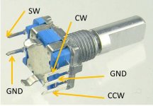
I am in the process of building this volume controller and hit a bump. Everything is soldered up and i am in the process of trying to set up the ldr controller. The problem is, when using the volume knob the rotation works but the click button isn't recognized. I am using this encoder. Cw, CCW and Gnd are connected on ABC. C and 2 is connected to GND and 1 to SW.
I don't have a remote to try the IR yet, so i can't find out if its a software or hardware issue.
Not sure if i interpreted the manual right... Any idea where i went wrong?
Last edited:
Hi to all of you,
I am in the process of building this volume controller and hit a bump. Everything is soldered up and i am in the process of trying to set up the ldr controller. The problem is, when using the volume knob the rotation works but the click button isn't recognized. I am using this encoder. Cw, CCW and Gnd are connected on ABC. C and 2 is connected to GND and 1 to SW.
I don't have a remote to try the IR yet, so i can't find out if its a software or hardware issue.
Not sure if i interpreted the manual right... Any idea where i went wrong?
Hi XC,
Could you perhaps post some photos showing how you connected the encoder?
Looks ok. Have you checked that the switch contacts are functioning when pressed? If the switch is working then I would do continuity checks between the SW pin at the encoder and the relevant pin on the Arduino board just to ensure there isn't a break anywhere. Do the same for GND.Hi win,
It is a bit hard to get a useful picture from inside. Also, my wires are twisted so its a bit hard to see which goes where ;-) I made an image where I illustrated what i connected where. Hope this makes it more clear what i did.
I checked for continuity and everything is fine. How do i check the switch contacts? Should there be continuity when i press the switch?
Yes, between the SW and adjacent GND pin on the encoder.I checked for continuity and everything is fine. How do i check the switch contacts? Should there be continuity when i press the switch?
awesome, thank you so much howart and wined! I just tried out manually shorting gnd and sw wire and it registered correctly 🙂)) I also checked the enocoder and it doesn't seem to short when i press the button. So i guess i have to order another one. Anyway, now I can keep testing on the weekend and see if i got the other stuff right 🙂
Last edited:
awesome, thank you so much howart and wined! I just tried out manually shorting gnd and sw wire and it registered correctly 🙂)) I also checked the enocoder and it doesn't seem to short when i press the button. So i guess i have to order another one. Anyway, now I can keep testing on the weekend and see if i got the other stuff right 🙂
Excellent, glad it was a simple fix. 🙂
I have built another one with 20x4lcd and all-in-one pcb. I have some extra boards if someone needs them. Works with latching relays and non balanced inputs only.

PCB can be used with external IO pcb as well, if you need to have latching relays and balanced IO.
PCB can be used with external IO pcb as well, if you need to have latching relays and balanced IO.
Last edited:
Thanks! I have a problem with apple remote though, it seems to be draining batteries. I measured resistance between contacts and it's 22k. Can someone check theirs so that I can compare?
Sent from my SM-G935F using Tapatalk
Sent from my SM-G935F using Tapatalk
This seems to work well for me Chris. Well done. I can't stick it in the wrong direction anymore.
Excellent work, works great now!
For folks like me with two outputs, you can use menu button for direct output switching:
case cIR_MENU:
if (state == STATE_IO) {
toRunState();
break;
}
else {
if (OUTPUTCOUNT > 1) {
chan_out = (chan_out + 1) % OUTPUTCOUNT;
setOutput();
}
break;
}
case cIR_MENU:
if (state == STATE_IO) {
toRunState();
break;
}
else {
if (OUTPUTCOUNT > 1) {
chan_out = (chan_out + 1) % OUTPUTCOUNT;
setOutput();
}
break;
}
I have one 3in balanced assembled pcb for sale since I don't use balanced inputs. Price will be the price of parts plus shipping. Ping me if interested.

Sent from my SM-G935F using Tapatalk
Sent from my SM-G935F using Tapatalk
- Home
- Source & Line
- Analog Line Level
- Arduino based LDR volume and source selection controller