I just checked all as suggested test points. No shorts anywhere. I will have to go through all component values with DMM and see if I got something wrong.
Are you using ksa992 and ksc1845?I just checked all as suggested test points. No shorts anywhere. I will have to go through all component values with DMM and see if I got something wrong.
Is the input shorted for adjusting offset?
Wouldn't it be a great idea to make a builders thread of this amp?
Wouldn't it be a great idea to make a builders thread of this amp?
Last edited:
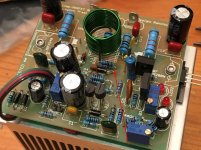
What is the value of these parallel resistors?
Looks like 1k(1k//1k=500ohm)?
R19=120ohm
Looks like 1k(1k//1k=500ohm)?
R19=120ohm
Attachments
Last edited:
What is the value of these parallel resistors?
Looks like 1k(1k//1k=500ohm)?
R19=120ohm
Good catch. I don't know how I messed that one up (actually I know. Working on it at 3am with no sleep 🙂 Thanks and good eyes!
Ok, the resistors for R19 are actually two 220R 1% and not 1k. The red almost looks brown. So value is 110R in parallel, I checked all resistors installed against the spreadsheet and they are good.
With circuit powered on, I measure 5.86v on the gate of the MOSFET. This results in 1.9v output which is what is causing offset.
Could the LED not be providing the correct voltage drop? Would using a 500R trimmer be causing my problems? There is absolutely no movement in the DC offset with the trimpot. I did ground the input pins.
The bias trimpot works though. Could it be a bad transistor? I checked the small signal ones and the KSA1381 with Hfe meter before installing and they appear good.
So running out of options here. How sensitive is all of this to the voltage drop by the blue LED vs the zener?
I am suspecting it may be the lack of 1N4004 diodes. They set the voltage drop across base and emitter of Q1. The FR104 diodes have a forward voltage drop of 1.3v vs the 1.0v of the 1N4004. Would this make a difference?
Maybe need to order diode and correct zener and retest...
Last edited:
Tell me what rail voltage you are running and I will give you some voltages to check for. That might help find the problem. I'm using the blue LED without issue so I doubt that is your problem. You should be seeing some movement when turning the pots. Maybe not enough but you should see something happening.
35volt rails. What about the 1N4004's? It's getting to be a bit frustrating now when I can't make any headway on this problem now. Absolutely no effect of offset when I turn the 500R pot. Nothing on the 100k pot worked either (R5). I even tried replacing 100k pot with plain resistor and still nothing.
Last edited:
Yeah, something else is wrong, I probably can't get to it until morning but I will take voltage measurements ASAP and post them. I know how frustrating it is when something doesn't work. Meanwhile. if you can without blowing something up, take VBE measurements on all of the BJT's and and make sure they are all around .6V.
Hi XRK,
I gotta get into this and try to help. I'm sorry you are in trouble, but it will be very simple once we find it. Measurement is the best way.
Now, index our circuit. You are working from Prasi's Rev 4.3 here?
http://www.diyaudio.com/forums/solid-state/255427-very-simple-quasi-complimentary-mosfet-amplifier-68.html
This is #675.
To find what's happening on the circuit, could you please measure these areas:
1. Voltage across Vbe multiplier, Q4, from C to E of BD139. Should be 1.90 volts
2. Voltage across LED and series 4004 diodes. Should be 3.25 volts
3. Voltage from gate of Q6 nmos to base of inverter, Q5. Should be 5.19 volts.
4. Voltage across R20, for 0.47R this should be around 50mV
5. Voltage at output wrt ground, should be 0mV but I think it's about +2? (positive?)
6. Voltage wrt ground at left side of VR1, should be -3.2V.
7. Voltage wrt ground at right side of VR1, should be -3.82V.
8. Voltage at wiper of VR1, and voltage at base of Q1, all wrt ground.
That should be enough to identify all currents and voltages around this circuit.
Good luck!
Hugh
XRK,
After reading through again I realise you have insufficient negative voltage on the base of Q4, and the reason is R4. REMOVE R4, it holds the base close to ground, and will not pull down by R5 under influence of the pot, VR1.
Just snip R4 - it is not needed, and in fact ground referencing for the signal is achieved at R1. R2 is the LP filter, working with C2, base to ground. You DO NOT NEED R4.
Hugh
Hugh,
Thank you for the detailed steps. Having probed around before you gave me this it was sort of all a shot in the dark. I will remove R4 but why does it work for others and not me? I pulled all the BJT's off and measured Vbe and 1381's are 0.62v, 1845 and 992 are 0.60v, and 2SC5200 is 0.495v. Seems a bit low but consistent with pristine one which measures 0.514v. I didn't pull BD139 off as the Vbe multiplier bias adjustment works.
So looks like all the transistors are good. The MOSFET does not show any signs of shorting out so probably good.
Thanks,
X
The value of R5, set 100k on Prasi's schemat, has a huge influence on the offset. If you set this around 33k, I would think it would be fine within the VR1 range, but when you increase R5 to 100k the dominant influence is earth, not the voltage at the wiper.
R5 sets the Zin of the input stage, and as you go up higher, the offset voltage rises over zero a lot, and BTW the resolution tends to drop too. I like to have my amp Zin around 33k, it's a good easy input load for the CD player, but not too high that introduces offset issues, noise, and poor resolution.
Does it work OK yet? I really would like to know whether it's fine now!
Hugh
Hugh,
Thank you for the detailed steps. Having probed around before you gave me this it was sort of all a shot in the dark. I will remove R4 but why does it work for others and not me? I pulled all the BJT's off and measured Vbe and 1381's are 0.62v, 1845 and 992 are 0.60v, and 2SC5200 is 0.495v. Seems a bit low but consistent with pristine one which measures 0.514v. I didn't pull BD139 off as the Vbe multiplier bias adjustment works.
So looks like all the transistors are good. The MOSFET does not show any signs of shorting out so probably good.
Thanks,
X
Hi X,
I think you misunderstood me when I asked you to measure the vbe of each BJT, I was referring to measuring the (V)oltage from (B)ase to (E)mitter (vbe) of each of them when powered up. That will many times reveal a bad transistor or a short or cold joint somewhere. If the vbe is close to .6V then you can look else where. It is just a simple test to look for problems in the circuit.
The value of R5, set 100k on Prasi's schemat, has a huge influence on the offset. If you set this around 33k, I would think it would be fine within the VR1 range, but when you increase R5 to 100k the dominant influence is earth, not the voltage at the wiper.
R5 sets the Zin of the input stage, and as you go up higher, the offset voltage rises over zero a lot, and BTW the resolution tends to drop too. I like to have my amp Zin around 33k, it's a good easy input load for the CD player, but not too high that introduces offset issues, noise, and poor resolution.
Does it work OK yet? I really would like to know whether it's fine now!
Hugh
Hi Hugh,
It was me who suggested using a 100k trimmer for R5. When I first built my amp the offset was very high. I found by installing a 100K trimmer and then setting VR1 to center I was able to adjust the trimmer in R5 until I had 0V offset. Then I measured R5 (trimmer) and it was about 50k so I installed a 51k resistor and was able to adjust the offset with VR1. However, I have R4 installed. I will try in the morning to lift R4 and see what I have then. I will also check for the voltages you suggest in post 771.
Thanks, Terry
Hi Terry,
Thanks for the post. I understand why you put in 100k but I'm not sure where the 47k R4 appeared. Certainly these are not serious issues and won't stop the amp. R5 should be set lower than that higher, however, and best not to use this value to adjust the offset; this should be done wimh the two led references to the left of VR1.
Sometimes I forget that these little differences are not understood; but this stuff is not easy, it needs a good background in Ohm and Kirchoff's Laws and a lot of people miss this stuff as they are educated. Again, it's not easy, and no one is to be blamed for any of it. Frankly I think the fact so many people are interested in DIY is amazing; there is a lot of hard work to learn the basics and most are happy to take it on.
Hugh
The value of R5, set 100k on Prasi's schemat, has a huge influence on the offset. If you set this around 33k, I would think it would be fine within the VR1 range, but when you increase R5 to 100k the dominant influence is earth, not the voltage at the wiper.
R5 sets the Zin of the input stage, and as you go up higher, the offset voltage rises over zero a lot, and BTW the resolution tends to drop too. I like to have my amp Zin around 33k, it's a good easy input load for the CD player, but not too high that introduces offset issues, noise, and poor resolution.
Does it work OK yet? I really would like to know whether it's fine now!
Hugh
Removing R4 at least lets the offset vary when I turn the Vr1 trimpot. The offset is now -1.7v and I can't get it any lower not matter what I do to the R5 100k pot. The amp seems to be behaving more like an amp now in that heat is being made. I tried playing music with the offset present and it doesn't sound good - highly distorted like going through massive crossover region (makes sense with large offset). Also, sound volume seems low.
I guess it is progress in that it responds at least.
On the other channel, I am able to adjust DC offset down to -1.3v.
Last edited:
Hi XRK,
We are making progress!
Do you have two redleds from ground to the left side of VR1?
If no, what is the voltage at left of VR1 wrt ground?
What value of R5 do you have? You might reduce it to the design value of 33k, then measure the offset again......
BTW, how much voltage is across R20, your source resistor on the mosfet? It should be at least 50mV if it's 0.47R.
Nearly there......
Hugh
Removing R4 at least lets the offset vary when I turn the Vr1 trimpot. The offset is now -1.7v and I can't get it any lower not matter what I do to the R5 100k pot. The amp seems to be behaving more like an amp now in that heat is being made. I tried playing music with the offset present and it doesn't sound good - highly distorted like going through massive crossover region (makes sense with large offset). Also, sound volume seems low.
I guess it is progress in that it responds at least.
Hi X,
Further to Terry's suggestion as per post #775, while measuring the voltages use any adjacent pads/ legs to which the tranny is connected to. This was suggested by Terry earlier in Apex thread and this lets you confirm proper soldering too in one go.
reg
Prasi
- Home
- Amplifiers
- Solid State
- Very simple quasi complimentary MOSFET amplifier