This is a lovely low parts count amp. Looks very build able in the 1.5hr class 🙂
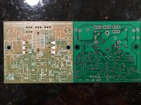
This matches rev 3 not 4.3. Look at LEDs.
This matches rev 3 not 4.3. Look at LEDs.
Attachments
Last edited:
Hi X.
Thimios and Ranchu too has careful changed any parts, can you find it?
Cheers. next 1,5hr.
Thimios and Ranchu too has careful changed any parts, can you find it?
Cheers. next 1,5hr.
I deduced that I have board Rev 3. Parts list and schematic here:
http://www.diyaudio.com/forums/soli...imentary-mosfet-amplifier-34.html#post4765108
hi x,
please refer post nos. 590/675 for latest component values. basis is post no. 564 as thiago said.
reg
prasi
Last edited:
Ok, thanks - I got the spreadsheet now.
Scanning through parts now and I believe I have everything in stock (or close with a few series or parallel resistors ). Hopefully some progress tonight. 🙂
Scanning through parts now and I believe I have everything in stock (or close with a few series or parallel resistors ). Hopefully some progress tonight. 🙂
Last edited:
I recommend installing a 100k trimmer for R5 and center VR1. Then adjust R5 until you have 0v offset. The amp has to fully warmed up to set it. Once you have it you can measure the R5 trimmer and then install the closest value resistor you have. I think mine ended up around 50k so I installed 51k and then adjusted VR1 from there. If you do have R5 right you may not have enough adjustment from the 200R (VR1) trimmer.
Build is completed but I am having problems with DC offset - can't get it to respond to any pot movement, it sits at 1.87v. I even put in the 100k pot at R5. The overall current into the amp is set at 150mA quiescent (as measured through 10R safety resistors on power supply rails). I am using a blue LED instead of the 3.2v zener. I tried playing music and the gain is very low - no volume at all. The second amp exhibits the same behavior, so whatever I am doing wrong seems to be affecting both equally. What is the startup sequence for setting the trim pots?
Any suggestions for debugging?

I ran out of 1N4004 diodes so am using FR104 (fast recovery rectifiers) - hope that is not causing the problem. I have correct 12v zener in place.
Any suggestions for debugging?
I ran out of 1N4004 diodes so am using FR104 (fast recovery rectifiers) - hope that is not causing the problem. I have correct 12v zener in place.
Attachments
Last edited:
How do you have the trimmer wired for R5? Do you have the center pin shorted to one of the other legs?
Yes, otherwise all I have is a 100k resistor 🙂
Other deltas from design due to lack of parts:
Big 2w power resistors on supply of MOSFET and emitter of BJT are 0.22 R not 0.33R. 2200uF feedback cap is only 470uF (need to order some more 2200uF 16v).
Other deltas from design due to lack of parts:
Big 2w power resistors on supply of MOSFET and emitter of BJT are 0.22 R not 0.33R. 2200uF feedback cap is only 470uF (need to order some more 2200uF 16v).
Last edited:
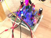
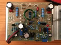
Size of pictures is small,we can see anything🙂Yes, otherwise all I have is a 100k resistor 🙂
Other deltas from design due to lack of parts:
Big 2w power resistors on supply of MOSFET and emitter of BJT are 0.22 R not 0.33R. 2200uF feedback cap is only 470uF (need to order some more 2200uF 16v).
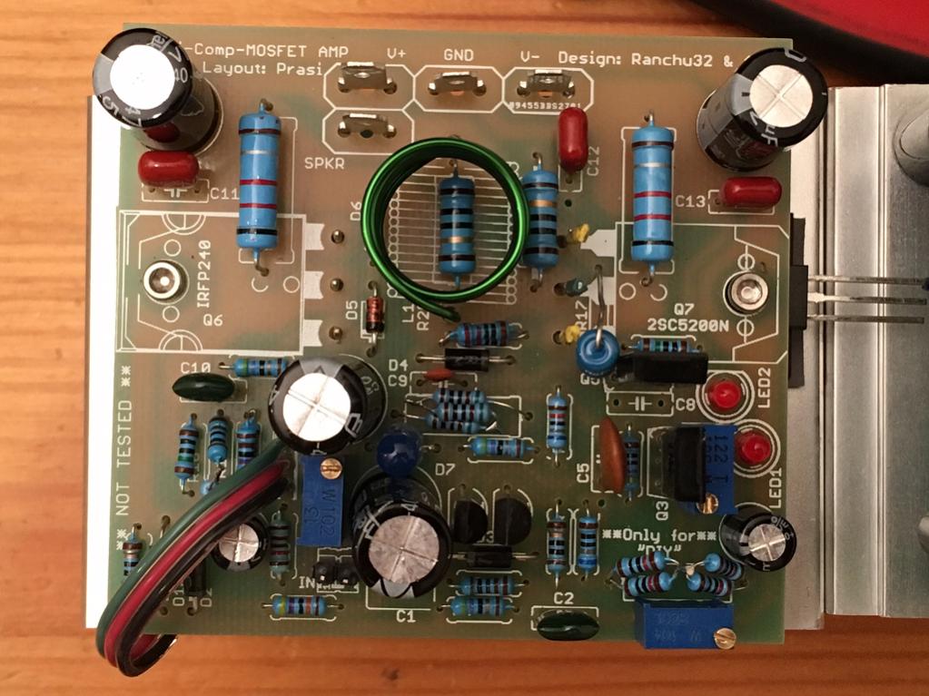

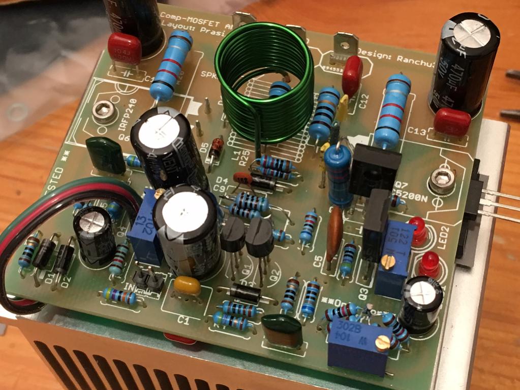


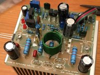
Ok, here are some better closeups for you - hopefully they will shed some light as to why this is not working.
One or two guesses are
1. Whether R9 is properly in contact with its pad ( do a continuity check from R9 to some other pad)
2. check for R8 and D7 short.
reg
Prasi
Attachments

Last edited:
Ok, here are some better closeups for you - hopefully they will shed some light as to why this is not working.
One or two guesses are
1. Whether R9 is properly in contact with its pad ( do a continuity check from R9 to some other pad)
2. check for R8 and D7 short.
reg
Prasi
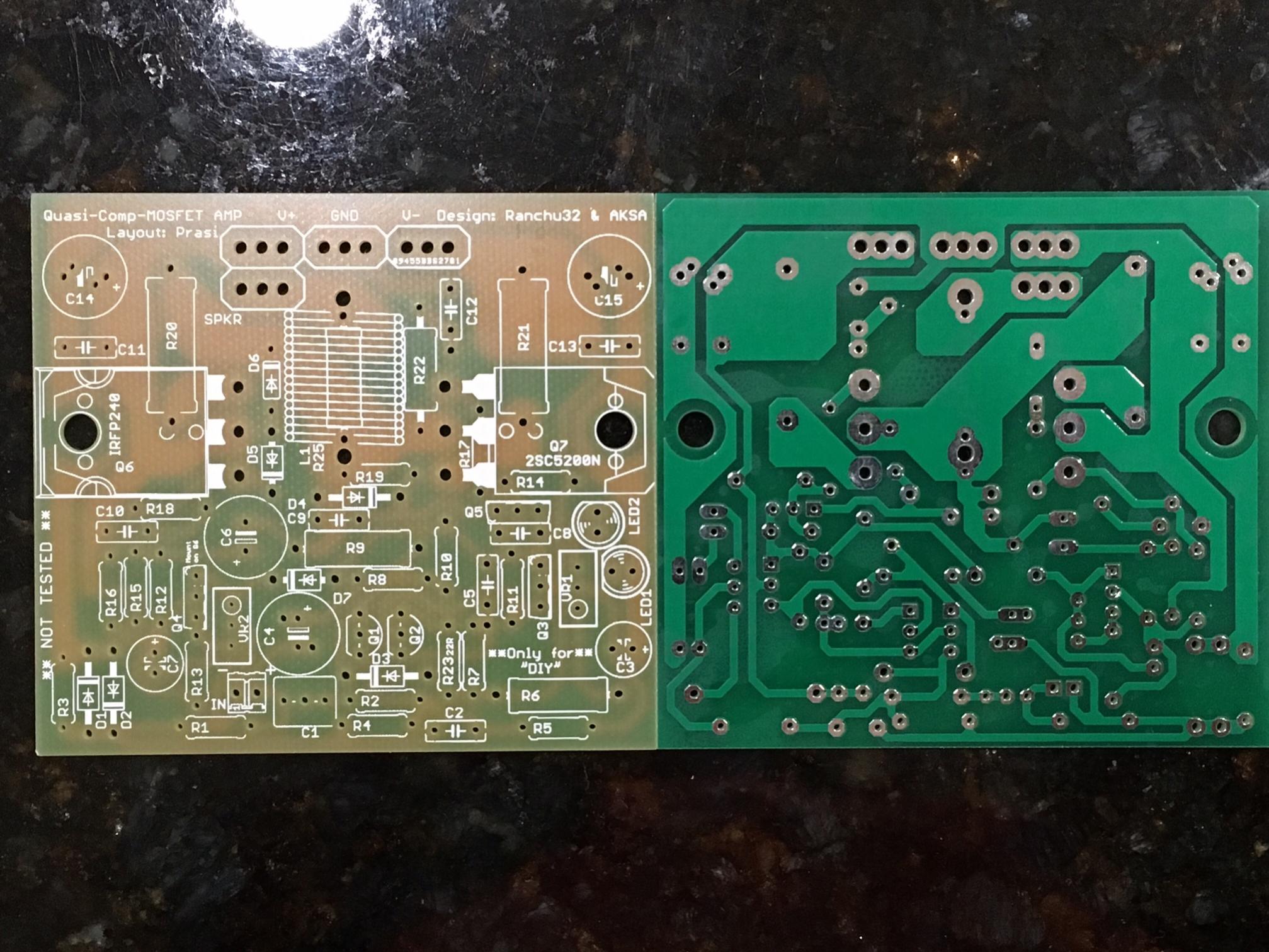
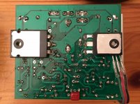
Thanks for the debugging tips. For easy reference, here is the unpopulated board so you can see labels and where problem areas such as shorts between R8 and D7 are.
One more thing, VR1 is 500ohm instead of 200ohm.
Last edited:
Thanks for the debugging tips. For easy reference, here is the unpopulated board so you can see labels and where problem areas such as shorts between R8 and D7 are.
One more thing, VR1 is 500ohm instead of 200ohm.
just posted an image, have a look. Also carefully check if R17 is touching any of the legs of TTC5200.
I will have to go and check shorts with continuity tester. The pins of 2SC5200 are not touching the resistor as I covered them with shrink tubing as you can see. Also, R17 is a big 2w unit that stands up rather horizontal.
Hi X.
Sorry, bad to read, you are now in pole position to find out- was prasis work well done,
we can observe.
You are the TestRabbid.
The Q3 should have a heat sink- is he touchable?
Any pages back Q3,5 dissipate ~188mW, don't know why Q5 without cooling?
Hugh wrote relation between source- gate resistor setting- higher Iq.
Must you higher the gate R to 180-220-270-300R, but bias is good, not necessary?
Hope you can find out what it is.
Cheers Bangla.
Hi X.
you are now in pole position to find out- was prasis work well done,
we can observe.
You are the TestRabbid.
What do you mean by "was prasi's work well done and you are the test rabbit?",
For your kind information, the layout exactly corresponds to the schematic and has been tested both by Thimios and Terry. Dont build, if you dont have confidence to build.
reg
Prasi
Hallo prasi.
Don't hate me, sorry for not good deliberated words, i have very much respect to all
the very nice work, done by all members here.
Sorry, sorry, i feel bad now. Should be only a little(tiny) joke, without ulterior motives.
reg Bangla.
Don't hate me, sorry for not good deliberated words, i have very much respect to all
the very nice work, done by all members here.
Sorry, sorry, i feel bad now. Should be only a little(tiny) joke, without ulterior motives.
reg Bangla.
Hallo prasi.
Don't hate me, sorry for not good deliberated words, i have very much respect to all
the very nice work, done by all members here.
Sorry, sorry, i feel bad now. Should be only a little(tiny) joke, without ulterior motives.
reg Bangla.
Its alright, no problems. Joke well taken😀. Just doing my bit here to help and learn things.
reg
Prasi
- Home
- Amplifiers
- Solid State
- Very simple quasi complimentary MOSFET amplifier