Hi terry, Decrease P1 value to 270Ω. frequency parameter is set 10kHz in your FH12.asc file.
That bounces the bias too 1.4A
That bounces the bias too 1.4A
You have adjust bias pot. You have a fixed resistor where the pit should be. The value, if using fixed is closer to 440ohms to get the right bias. But this is with the original 150R LTP resistor.
Last edited:
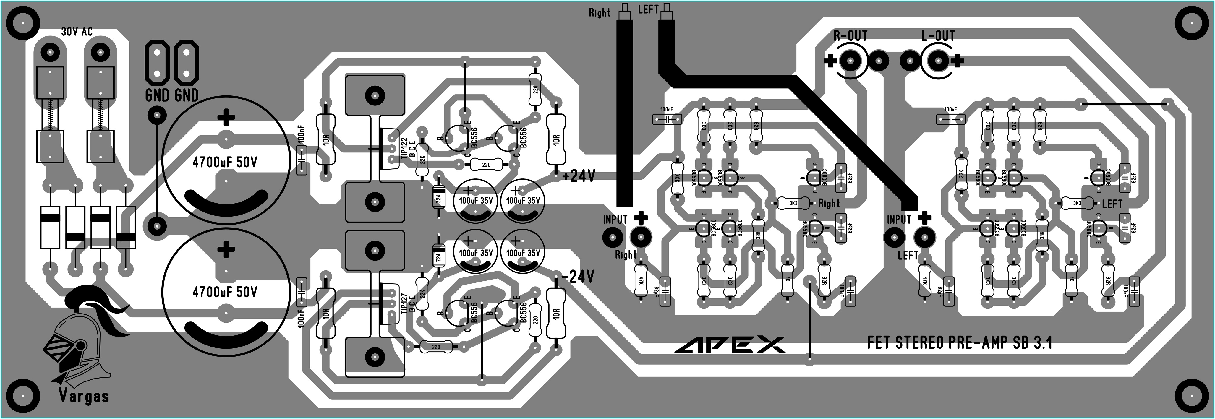
Thank you, Benz. I thought it was a further improved SB3.1 version using FETs at differential, but probably Apex Audio did something similar with the P30.
--------------------------------
Thanks anyway, and also for Juan Vargas' brilliant layout. 🙂
I'm busy with DIY preamps lately...
You have adjust bias pot. You have a fixed resistor where the pit should be. The value, if using fixed is closer to 440ohms to get the right bias. But this is with the original 150R LTP resistor.
I'm running it is spice. Actual values my change in real life depending on device tolerances. I am assuming that Sonal ran my file in spice as well.
Sonal, The 10K can be changed to whatever you want by editing the
param freq line in the SPICE directive.
Does anyone know what the gain is for the SB 3.1 BJT preamp and which resistors control it?
Thanks...
Thanks...
I made FH12 mod.
The bias current might be slightly over compensated, but I trade it for simple construction.
This is the simulation file.
Can't run it. Too many models that are not available.
Can't run it. Too many models that are not available.
The models:
Attachments
So how does it look in LTSpice? Similar to what I was getting in Tina?
I convert it to pdf file.
Attachments
Change of transistors and a few resistor values was very good. 0.0026%THD now vs 0.04% before. Nice!
Change of transistors and a few resistor values was very good. 0.0026%THD now vs 0.04% before. Nice!
Cascaded 'current mirror' was a raw idea from Mile. It is a raw design. Later on Mile suggesting on improving it with a maximum of 2mA for LTP ccs, maximum of 30mA for VAS and adding a (mosfet/bjt) driver stage...
The above requires changes to the components as implemented by Bimo...
But even without the driver stage, you can still have better performance than the raw idea/design. THD of 0.004% (or probably lower) is possible.
Many amplifiers use it to reduce transistor dissipation, like Symasym. Because the transistor do not need to swing too much voltage. You can also use resistor and capacitor (parallel), if you want more cheap solution.
Cascaded 'current mirror' was a raw idea from Mile. It is a raw design. Later on Mile suggesting on improving it with a maximum of 2mA for LTP ccs, maximum of 30mA for VAS and adding a (mosfet/bjt) driver stage...
The above requires changes to the components as implemented by Bimo...
But even without the driver stage, you can still have better performance than the raw idea/design. THD of 0.004% (or probably lower) is possible.
I was looking at the schematic on my phone and missed the fact there were two more drivers. LOL - because it wasn't called FH14 yet. Ok it's not such a simple thing anymore. The FH9 was simple and sounded great.
This one is more along the lines of a much more refined amp. Less raw.
Someone should build it though. We need an updated layout from one of the masters Prasi or Sonal. 🙂
Many amplifiers use it to reduce transistor dissipation, like Symasym. Because the transistor do not need to swing too much voltage. You can also use resistor and capacitor (parallel), if you want more cheap solution.
Resistor and capacitor is not cheaper than transistor and use more space on pcb 😉
Many amplifiers use it to reduce transistor dissipation, like Symasym. Because the transistor do not need to swing too much voltage. You can also use resistor and capacitor (parallel), if you want more cheap solution.
I wasn't specifically talking about the cascaded transistors tho explicitly it seemed so. Hopefully nobody think that I said that Mile invented the cascaded transistors idea 😀
Hi all.
For my little understanding: is that a 3EF called schematic?
Cheers Bangla
BX20 output stage is triple emiter folower.
- Home
- Amplifiers
- Solid State
- 100W Ultimate Fidelity Amplifier