I notice that some of Mr. Mile's circuits don't have inductors at the output.
Do you have to use an inductor for the FH11/12?
Do you have to use an inductor for the FH11/12?
I notice that some of Mr. Mile's circuits don't have inductors at the output.
Do you have to use an inductor for the FH11/12?
Inductor and resistor in parallel is used for stability against capacitive load. Doesn't hurt to add inductor since there's lots of space left in layout.
Scroll down to Output Stage Stability.
Let's call it FH12
Hi Terry,
Is there a missing junction where M4 and M3 connect to out?
reg
prasi
Inductor and resistor in parallel is used for stability against capacitive load. Doesn't hurt to add inductor since there's lots of space left in layout.
Scroll down to Output Stage Stability.
How many turns of insulated wire and what size drill bit is needed to wrap it around?
Thanks...
Hi Terry,
Is there a missing junction where M4 and M3 connect to out?
reg
prasi
Yes, good catch. I may have other things not quite right. The THD is quite high,
Let's call it FH12
Nice work, use 390R instead 150R for R1...
between 7turns and 11turns wrapped around an AA battery, gives approx 0.7uH to 1.5uHHow many turns of insulated wire and what size drill bit is needed to wrap it around?
Thanks...
Use thick enameled copper wire. At least 1mm diam, but preferably >1.6mm diam.
Keep the inductor away from the amplifier PCB and away from metal panels.
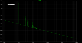
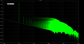
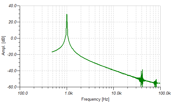
FFT of FH11/12 with R1= 150Ω and 390Ω.
With R1 150R LTP current will be 5mA per transistor and VAS current will be about 50mA, it is to high, 2mA for LTP and 30mA for VAS is maximum.
Add BJT or mosfet drivers for low THD.
Attachments
Last edited:
Yes, good catch. I may have other things not quite right. The THD is quite high,
My sims of FH11 in Tina had THD of 0.04% at full power. That was with a single transistor - I am not sure if adding another active just to reduce power dissipation is worth the complexity and pushing the number from FH11 to FH12. A larger heatsink would have sufficed as Terry said.
Is the grass in the 390r fft due to the reduced LTP current and reduced VAS current, or due to a change in the way you asked the question of the model?FFT of FH11/12 with R1= 150Ω and 390Ω.
If the grass is real distortion, then it shows the odd harmonics above 3rd increasing badly.
If this is the case you need to separate the two current changes and only change one current at a time. See which current needs to remain high to get the left hand simulation fft.
Then find out how low it can go before the distortion takes off.
Finally you need to look at compensation to find if there is instability that is causing the big increase in distortion when the current is lower.
Last edited:
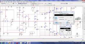
FH12 model in Tina
Nice layout Sonal! I like it.
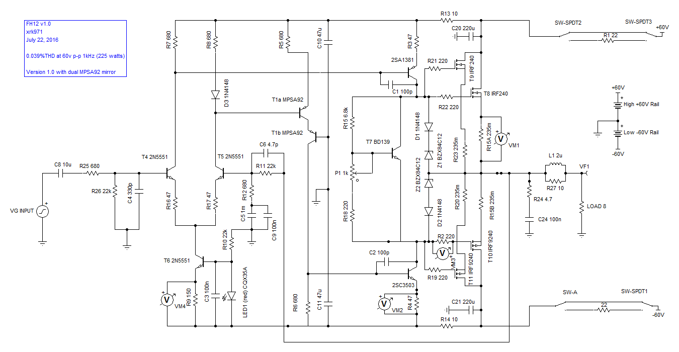
My model of the dual MPSA92 mirror seems to work pretty well, in fact, the THD even went down a tad from 0.044% to 0.039% for 1kHz 60V peak-peak output. I am using KSC3503/KSA1381 for the VAS. Current at LTP is 5mA and current at VAS is 20mA. The sims on Tina seem consistent with measurements of clean square waves and listening impressions of good sound (not high harmonic distortion).
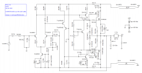
Schematic:
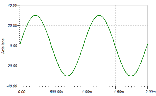
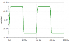
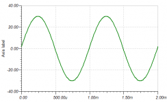
1kHz Sine Wave 60V p-p:
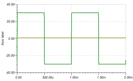
1kHz Square Wave 60V p-p:
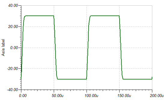
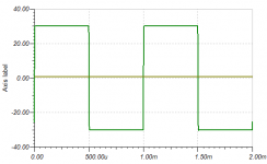
10kHz Square Wave 60V p-p:
Spectrum with 1kHz input:
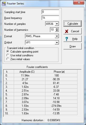
Calculated FFT HD components with THD=0.039%:
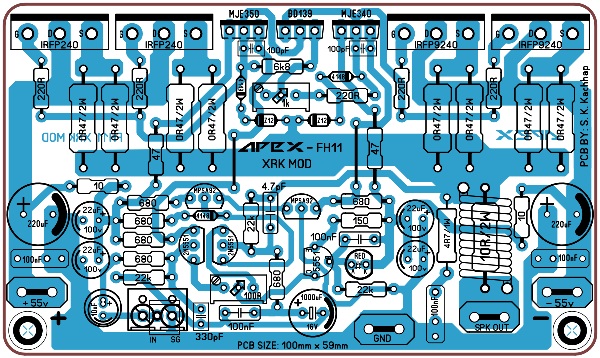
FH11 with modifications suggested by Mr. Miles.
@XRK, could you update schematic with modifications.
@Bangla H, I use sprint layout easy to use but more likely I make mistake while drawing layout. But it's fun once you get hang of it.
I started with eagle and still use it for digital layout.
Nice layout Sonal! I like it.
My model of the dual MPSA92 mirror seems to work pretty well, in fact, the THD even went down a tad from 0.044% to 0.039% for 1kHz 60V peak-peak output. I am using KSC3503/KSA1381 for the VAS. Current at LTP is 5mA and current at VAS is 20mA. The sims on Tina seem consistent with measurements of clean square waves and listening impressions of good sound (not high harmonic distortion).
Schematic:
1kHz Sine Wave 60V p-p:
1kHz Square Wave 60V p-p:
10kHz Square Wave 60V p-p:
Spectrum with 1kHz input:
Calculated FFT HD components with THD=0.039%:
Attachments

Last edited:
will test Eagle first
Hallo sonal.
Thanks for advise too.
I will start with Eagle- my first steps there.
Your FH11 wow- very compact- good to mount on any heat sinks.
http://www.diyaudio.com/forums/atta...-fidelity-amplifier-fh11-100x60mm-ver1.04.png
I follow the impressing pull out of ideas- it's funny- only wow! 😱
 Bangla.
Hallo sonal.
Thanks for advise too.
I will start with Eagle- my first steps there.
Your FH11 wow- very compact- good to mount on any heat sinks.
http://www.diyaudio.com/forums/atta...-fidelity-amplifier-fh11-100x60mm-ver1.04.png
I follow the impressing pull out of ideas- it's funny- only wow! 😱
Bangla.Adjust the pot to get 42mV across the supply resistors (0.235ohm) for 180mA quiescent current. That pot and 220R combo is pretty critical.
With capacity multiplication in each OP PS, and constant current source with fet in differential pair, SB3.1 [preamp] can be upgrade in higher sound quality.
Maybe you have already presented it, but if not, would you?
- Home
- Amplifiers
- Solid State
- 100W Ultimate Fidelity Amplifier