2nd heel
Besides working a bit in the garden and pondering about how exactly I'm going to implement the room treatment, I've finished the tweeter heads.


Looking good even if I say so myself 😀
I've also been measuring and trying to fix some of the distortion.
The problem is probably due to the way I make the 2 compartments in the basscab. I use the drilled out pieces from the bracing as plugs with 4mm isolation foam, stuff them in the holes and attach a piece of leftover birchply to connect 3 for extra stability.
Some pics for clarification.

Driver protected from the fibreglass damping with a nice piece of felt (got the idea from 2 towers, works very nice)

I had to remove a lot of tacks to be able to get at the bracing.
When it was still a 3-way I had no problem with this method to separate the compartments but the 22W was in 50l separated from the other 20l.

This was with 22W, 10F and ND25FA
After adding the 26W, the 22W only had 20l and both woofers were pushing on the plugs. This caused some very audible resonance problems because the connecting piece was bouncing on the bracing.

After sawing of the noisy excess piece things were much better.

Now, with the addition of the Satori and SB26ADC I wanted to improve the separation of the cabinets because after my previous quick fix the plugs were obviously still moving just not as loud as before. So I added an extra piece of connecting birch ply to the bottom in order to stabilize and stiffen the separation.


Pretty much -50dB from where the satori and SB26ADC pick up but the 22W has a big 3e order peak at 200 (still only -43dB)
Comparing to the 3way which didn't have the basscab separation issue it's nice to see the improvement from 300 on up but still leaves some room for the <300 range.
Besides working a bit in the garden and pondering about how exactly I'm going to implement the room treatment, I've finished the tweeter heads.
Looking good even if I say so myself 😀
I've also been measuring and trying to fix some of the distortion.
The problem is probably due to the way I make the 2 compartments in the basscab. I use the drilled out pieces from the bracing as plugs with 4mm isolation foam, stuff them in the holes and attach a piece of leftover birchply to connect 3 for extra stability.
Some pics for clarification.
Driver protected from the fibreglass damping with a nice piece of felt (got the idea from 2 towers, works very nice)
I had to remove a lot of tacks to be able to get at the bracing.
When it was still a 3-way I had no problem with this method to separate the compartments but the 22W was in 50l separated from the other 20l.
This was with 22W, 10F and ND25FA
After adding the 26W, the 22W only had 20l and both woofers were pushing on the plugs. This caused some very audible resonance problems because the connecting piece was bouncing on the bracing.
After sawing of the noisy excess piece things were much better.
Now, with the addition of the Satori and SB26ADC I wanted to improve the separation of the cabinets because after my previous quick fix the plugs were obviously still moving just not as loud as before. So I added an extra piece of connecting birch ply to the bottom in order to stabilize and stiffen the separation.
Pretty much -50dB from where the satori and SB26ADC pick up but the 22W has a big 3e order peak at 200 (still only -43dB)
Comparing to the 3way which didn't have the basscab separation issue it's nice to see the improvement from 300 on up but still leaves some room for the <300 range.
Last edited:
Agree tweeter head look good work be proud of that : )
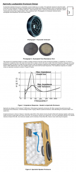
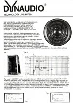
I'm not a expert about distortion performance for 22W but you share some pretty good data so one starts think, and have seen before someone mention that certain drivers don't like when volume get lowered below a certain point without a penalty in distortion for some regions. If that is situation with 22W you can try a resistive vent on backside of box which will make 22W see a much bigger volume closer to OB behavior. Below is some paper had on HDD, vent is pretty simple construction so suggest not to buy the expensive SS one, but instead diy out of vent stuff from a local diy store.
I'm not a expert about distortion performance for 22W but you share some pretty good data so one starts think, and have seen before someone mention that certain drivers don't like when volume get lowered below a certain point without a penalty in distortion for some regions. If that is situation with 22W you can try a resistive vent on backside of box which will make 22W see a much bigger volume closer to OB behavior. Below is some paper had on HDD, vent is pretty simple construction so suggest not to buy the expensive SS one, but instead diy out of vent stuff from a local diy store.
Attachments
Last edited:
Thanks for the suggestion BYRTT, there is a very interesting thread about using these resistive vents on the sides of an enclosure in order to control dispersion by using a bit of the backwave to cancel part of the front wave significantly lowering the frequency were the speaker becomes a monopole. Kinda like the KII Three but a passive solution. I might try this in the distant future 🙂
If I compare the distortion of the 4-way after the quick fix with the distortion after mounting the double connecting birch ply some things improve.
The 2nd order peaks at 66 and 100 are gone but the 3rd order peak at 200 is larger (you can even see it a bit in the quiet measurement). For a better comparison I should have measured at the same SPL but these are measurements taken over the course of the past 6 months.
This leads me to believe that it's the compartment separation that is to blame. I'll try if I can "tune" the distortion by tightening or loosening the screws that hold it together, maybe I can get it stiff enough so it doesn't get excited.
Otherwise I'll have to see if I can damp it sufficiently by putting some rubbery thing between the connecting pieces and the bracing. I'm a bit wary about just gluing it shut because I might someday change over to double 10s and the basscabs cost about 500€ in materials and 3-4 weeks to build.
If it does turn out to be the small volume for the 22W I'll build a test enclosure and work with that before taking a drill and saw to my basscabs 😉
I've tried fastening the screws, loosening the screws. I put felt between the ply connecting pieces and the bracing/plugs. I even changed amps, nothing changes the distortion peak at 200Hz. Looks like I'll be making a test enclosure. I'm not in a big hurry though, -43dB isn't the end of the world.
The rockwool damping is coming on wednesday so I can start some experiments on room treatment.
I've also made a nice little speaker cabinet for the 10F and ND25FA so I can use them as pc speaker. I'll make a separate post about it when I'm done learning how to build a passive crossover. Xsim here I come.
Nice speaker.
Hard work here!
You tell me you will analyze 22w in test box. I guess you always have this problem.
Maybe 22w and 26w cabinet are not well damp proof like you say.
Air flow of 26w can disturb the membrane of 26w. Maybe...
An another way, 26w and 22w are closed each other. So adding 26w can create vibrations in the front baffle.
You could try to cutoff frequency of the 26w high pass to 50hz or little higher.
If distorsion decrease the thickness of front baffle could be the problem.
Hard work here!
The problem is probably due to the way I make the 2 compartments in the basscab. I use the drilled out pieces from the bracing as plugs with 4mm isolation foam, stuff them in the holes and attach a piece of leftover birchply to connect 3 for extra stability.
Some pics for clarification.
View attachment 542149
You tell me you will analyze 22w in test box. I guess you always have this problem.
Maybe 22w and 26w cabinet are not well damp proof like you say.
Air flow of 26w can disturb the membrane of 26w. Maybe...
An another way, 26w and 22w are closed each other. So adding 26w can create vibrations in the front baffle.
You could try to cutoff frequency of the 26w high pass to 50hz or little higher.
If distorsion decrease the thickness of front baffle could be the problem.
Besides working a bit in the garden and pondering about how exactly I'm going to implement the room treatment, I've finished the tweeter heads.
View attachment 542151
View attachment 542152
Looking good even if I say so myself 😀
I've also been measuring and trying to fix some of the distortion.
The problem is probably due to the way I make the 2 compartments in the basscab. I use the drilled out pieces from the bracing as plugs with 4mm isolation foam, stuff them in the holes and attach a piece of leftover birchply to connect 3 for extra stability.
Some pics for clarification.
View attachment 542149
Driver protected from the fibreglass damping with a nice piece of felt (got the idea from 2 towers, works very nice)
View attachment 542150
I had to remove a lot of tacks to be able to get at the bracing.
When it was still a 3-way I had no problem with this method to separate the compartments but the 22W was in 50l separated from the other 20l.
View attachment 542144
This was with 22W, 10F and ND25FA
After adding the 26W, the 22W only had 20l and both woofers were pushing on the plugs. This caused some very audible resonance problems because the connecting piece was bouncing on the bracing.
View attachment 542145
After sawing of the noisy excess piece things were much better.
View attachment 542146
Now, with the addition of the Satori and SB26ADC I wanted to improve the separation of the cabinets because after my previous quick fix the plugs were obviously still moving just not as loud as before. So I added an extra piece of connecting birch ply to the bottom in order to stabilize and stiffen the separation.
View attachment 542147
View attachment 542148
Pretty much -50dB from where the satori and SB26ADC pick up but the 22W has a big 3e order peak at 200 (still only -43dB)
Comparing to the 3way which didn't have the basscab separation issue it's nice to see the improvement from 300 on up but still leaves some room for the <300 range.
Really good distortion limits.
Could you provide some details about your measurement setup?
@ Frank: measurements with the testbox coming up tomorrow. We'll see if it's due to the small volume and the flow resistor can fix it or not.
@ Jojip: I measure at 1m tweeter height using UMIK and REW, speakers pulled 2m from back wall with about 30cm high pile of blankets and pillows between speaker and mic.
@ Jojip: I measure at 1m tweeter height using UMIK and REW, speakers pulled 2m from back wall with about 30cm high pile of blankets and pillows between speaker and mic.
So, it's time for Fun with Graphs 🙂
First some pics of the test box. It's about the same volume as the 22W compartment in the speakers and made from cheap plywood. I added a bit of polyester fluff (much much less damping then the 22W cabinet filled with rockwool). It looks bad but I put silicone sealant on all glued inside corners and a foam sealing band between the box and the front and back baffle.

On the back I made 6 slits 18mm wide, behind the slits is a piece of felt pressed firmly between 2 pieces of ply. I can cover the slits with screws and pieces of ply.

Onward with the distortion measurements 22W was run full range, no crossover.
All slits closed

2 slits open

all slits open

broad 3rd order peak at 200 is gone new 3rd order peak at 130
driver without baffle on the ground mic at 1m

driver without baffle on the ground mic at 20 cm

Broad 3rd order peak at 250-300.
I can't really make anything out at the moment but wanted to share the measurements. I'll probably think of something this evening.
First some pics of the test box. It's about the same volume as the 22W compartment in the speakers and made from cheap plywood. I added a bit of polyester fluff (much much less damping then the 22W cabinet filled with rockwool). It looks bad but I put silicone sealant on all glued inside corners and a foam sealing band between the box and the front and back baffle.
On the back I made 6 slits 18mm wide, behind the slits is a piece of felt pressed firmly between 2 pieces of ply. I can cover the slits with screws and pieces of ply.
Onward with the distortion measurements 22W was run full range, no crossover.
All slits closed
2 slits open
all slits open
broad 3rd order peak at 200 is gone new 3rd order peak at 130
driver without baffle on the ground mic at 1m
driver without baffle on the ground mic at 20 cm
Broad 3rd order peak at 250-300.
I can't really make anything out at the moment but wanted to share the measurements. I'll probably think of something this evening.
Last edited:
So, it's time for Fun with Graphs 🙂
First some pics of the test box. It's about the same volume as the 22W compartment in the speakers and made from cheap plywood. I added a bit of polyester fluff (much much less damping then the 22W cabinet filled with rockwool). It looks bad but I put silicone sealant on all glued inside corners and a foam sealing band between the box and the front and back baffle.
View attachment 560912
On the back I made 6 slits 18mm wide, behind the slits is a piece of felt pressed firmly between 2 pieces of ply. I can cover the slits with screws and pieces of ply.
View attachment 560913
Onward with the distortion measurements 22W was run full range, no crossover.
All slits closed
View attachment 560914
2 slits open
View attachment 560915
all slits open
View attachment 560916
broad 3rd order peak at 200 is gone new 3rd order peak at 130
driver without baffle on the ground mic at 1m
View attachment 560917
driver without baffle on the ground mic at 20 cm
View attachment 560918
Broad 3rd order peak at 250-300.
I can't really make anything out at the moment but wanted to share the measurements. I'll probably think of something this evening.
Great thanks sharing 😎.
Suggest try narrow (thin) strips of carpet or gaffa tape on back or front of cone, three to five pieces or even more and place them maybe as the slits on the SS top series, thought is you try mod out into new test enclosure and should be easy to remove again.
If you have some tool for task think also would be interesting to see where and how impedance looks into test enclosure 🙂.
All slits closed
View attachment 560914
2 slits open
View attachment 560915
all slits open
View attachment 560916
broad 3rd order peak at 200 is gone new 3rd order peak at 130
I don't see really difference of distorsion between closed, 2 slits ans all slits open.
200hz peak isn't here in test box, like your measures of cabinet without 26w.
For me 200hz peak comes from 26w.
About the peak at 130hz, it's not new.
You have it in your speaker but it less strong.
Don't forget the highpass at 120-200hz, you have less power than using no filter. So distorsion decreases but peak is still here.
Courage!

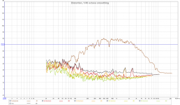
Distortion measurement of speaker with denon AVR3806 set to pure direct (it shouldn't do any bass management to the front speakers with this setting)

Peak at 200 visible, lots of other weird peaks.
Distortion of speaker with denon AVR 3806 set to stereo (it should cross the mean speakers over to the sub at 40-60-80-100 or 120 Hz)

Peak at 200 visible, weird other peaks are gone.
Distortion without 26W playing

Distortion without 22W playing

Only 22W playing

Only 26W playing

1) The peak at 200 is due to the 22W
2) Weird stuff is happening when in "pure" mode
3) In order to find out what's happening in 2) I should get measurements over HDMI to work, I have tried a few times but I always get measurements full of dips and peaks.
I always measure using the analog output of my soundcard to analog in on AVR, pre-out on AVR to analog in on Najda crossover. I always listen via HDMI to AVR, pre-out on AVR to analog in on Najda crossover and when listening there are definitely no dips and peaks as huge as on the measurements.
But first I'll try to find what is causing and fix the 3rd order peak at 200Hz for the 22W
Peak at 200 visible, lots of other weird peaks.
Distortion of speaker with denon AVR 3806 set to stereo (it should cross the mean speakers over to the sub at 40-60-80-100 or 120 Hz)
Peak at 200 visible, weird other peaks are gone.
Distortion without 26W playing
Distortion without 22W playing
Only 22W playing
Only 26W playing
1) The peak at 200 is due to the 22W
2) Weird stuff is happening when in "pure" mode
3) In order to find out what's happening in 2) I should get measurements over HDMI to work, I have tried a few times but I always get measurements full of dips and peaks.
I always measure using the analog output of my soundcard to analog in on AVR, pre-out on AVR to analog in on Najda crossover. I always listen via HDMI to AVR, pre-out on AVR to analog in on Najda crossover and when listening there are definitely no dips and peaks as huge as on the measurements.
But first I'll try to find what is causing and fix the 3rd order peak at 200Hz for the 22W
Attachments

The vents seem to work as advertised in reducing the impedance peak. Too bad it doesn't fix the distortion peak.
I'm considering going for the new 9 inch Satori wo24p-8 when funds allow. I can start with 1 per speaker and have volume enough in the basscabs to add a second later. This makes it a 3-way so I can ditch an amp and I would be able do the sub crossover in Najda. Together with a raspberry pi with digital audio out I can also ditch the denon from the system and use Najda as a proper preamp for stereo.
Last edited:

I finished the bass-trap (30x60x240cm) it should work best for frequencies between 285Hz and 140Hz. It's in the only corner I can put it and it's the largest I can make it. But that range happily coincides with the excess energy i have between 100 and 300 at the listening position. My girlfriend still hasn't picked a nice picture to have printed on cloth to wrap the trap. I'm hoping having it there in all it's rockwoolish glory might speed up that process 😉.
So I made a bunch of measurements. 3 positions, 2 speakers and 3 settings (full range, crossed at 40Hz and crossed at 80Hz to sub) with and without rockwool in the trap for a grand total of 36 measurements (some discarded due to weird artifacts in the measurements)
I've been playing with the RT60, decay, waterfall and spectrogram plots in REW. sp1 means speaker 1 and is the one closest to the trap, pos 1 means position 1 and is the one closest to the trap. Darker colors are without damping in the trap, lighter colors are with damping. Plots are for T20.


If you squint you might be able to see that on average the T20 of the lighter colors falls below the T20 of the darker colors. 😀
And some measurements of frequency response (4 sample window) at the listening position. Lighter colors with damping in trap.
Averaged over positions

Averaged over positions and speakers

Averaged over positions
Averaged over positions and speakers
Added some rockwool panels to strategic locations.


T20 times for all positions, no sub this time. Red is without trap and no panels, green is with trap no panels and blue is with trap and panels.

Getting usefull info out of the impulse, decay, waterfall and spectrogram graphs turns out to be more difficult then I expected.
T20 times for all positions, no sub this time. Red is without trap and no panels, green is with trap no panels and blue is with trap and panels.
Getting usefull info out of the impulse, decay, waterfall and spectrogram graphs turns out to be more difficult then I expected.
Last edited:
- Status
- Not open for further replies.
- Home
- Loudspeakers
- Multi-Way
- Achilles FIR 4-way