No, those BCs are candidate to replace Nichicon PW in C1 and C2 (LM3886 decoupling)
Ahh ok. Sorry for mistake.
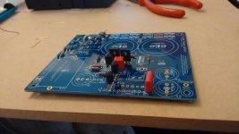
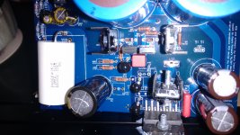
In attach you can find some photo of my build in progress
Attachments

Ahh ok. Sorry for mistake.
Nothing to be sorry of. 😉
In attach you can find some photo of my build in progress
Looks good so far 🙂
If they'll resist time proof (and burn in) they will replace Nichicon PW in the industrial BOM.
They didn't...
As time passed they lost most of the good things.
I'm thinking to revert C1 and C2 to the original capacitor, Panasonic FM, which is less fussy than Nichicon PW matching with the rest of the setup.

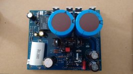

pic of my finished build 🙂
It was quite a ride for me because this was pretty much my first time building something like this. Especially the SMD was quite a learning experience, but after getting used to it, it was a lot of fun. I used cerafines, amtrans and mcap supreme. Only R10 with a Z-foil (error in ordering). I am thinking about replacing R12, but not sure because I am very happy with the sound already. Hard to imagine what else could improve.
I really love how this amp sounds. Had some worries about the base sounding a little bit muddy, but after maybe 25-30 hours of break in the sound signature changed a lot. Now it is very well defined and balanced. Mids are very detailed, good separation, highs are awesome - very clear and natural sounding without being bright.
Altogether really an amazing sounding amp. Can't stop singing along with my favourite songs now *lol*
Attachments

I finished to solder all components... now I have to cable and run...
In attach some images.
Looks good 🙂
Remember to solder LM3886s before powering up...
 😀
😀pic of my finished build 🙂
Good job! 🙂
I am thinking about replacing R12, but not sure because I am very happy with the sound already. Hard to imagine what else could improve.
Enjoy it, you can upgrade it later 😉
Nevertheless... it will improve with further upgrades

I really love how this amp sounds.
(...)
Altogether really an amazing sounding amp. Can't stop singing along with my favourite songs now *lol*

pic of my finished build 🙂
Very nice!
What amplifier have you used before? Can you make some comparison?
Problem with one channel
Hi all
this evening I try to do some test on my new build with wave generator and oscilloscope.
One channel seems ok. Put 200mV at 1KHz and obtain 2V. There is a lot of noise but problably depends on connection...
The second channel doesn't work. If I put some wave in input I have a distorted output and often the led goes off. Probably he go in protection mode.
I welded both channel in parallel...
Can you help me?
It seems that there is a signal to high frequency with gigh voltage (more that 2V) at input of lm3886 (pin 10).
I'm not able to understand where this signal is genearted because when I put the probe on one pin (R12, C34, lm3886 pin 10) protection go on.
The second channel doesn't work. If I put some wave in input I have a distorted output and often the led goes off. Probably he go in protection mode.
I welded both channel in parallel...
Can you help me?
Post some good quality pictures, please.
Let's see if there's something wrong.
Did you clean boards?
Did you take the indicated measures?
troystg: yes plenty of space. Wanted to keep the option for 4 channels open. And the price difference for smaller cases is negliable anyway 😀
dario: yeah, especially R12 since you put it up so high on the modding list *ggg* Ah, well ... first finish volume control and dac, then i have earned some more money for z-foil 😉
rookie: well let me try. Its hard to do an AB comparison since I also modded my speaker crossover after building this amp. I used a yamaha ax-496 with Infinity RS 5000 speakers.
The first big difference i noticed was the soundstage. It really made it sound like the music was not coming from the speakers anymore. Very good separation and placement. Also, it definitely has this "tube-touch" not as extreme as with a normal tube amp, but to get an idea what it sounds like a very good picture. The voices now sound a lot more realistic to me. Now i sometimes hear a noise and only afterwarsd realize it was from the recorded music/movie *ggg* In my eyes a really worthwhile build with incredible bang for buck ( aaaand i went some 200 eur over budget since this was my first build and i needed to buy lots of tools and decided to go for some upgrades - so beware ;-) )
a general question - any of you has any experience with shielding? The amp is super robust and doesn't mind, but my dac seems to picks up EMI from lightbulbs(halogen) and the fridge. I do use a line filter before the psu, so i assume it comes from EMI, not over the power line. What materials would you suggest? mumetal?
Sort the fridge first. Fit a mains snubber across the motor, or replace the faulty one. It is always better to sort interference at source. The regulations require source to be properly RF attenuated........... my dac seems to picks up EMI from lightbulbs(halogen) and the fridge.
Halogen lights are just resistors. They produce VERY little emi.I do use a line filter before the psu, so i assume it comes from EMI, not over the power line. What materials would you suggest? mumetal?
Your problem is more likely to be the SMPS used to convert mains 220/240Vac down to the 12V required by the resistive filament.
How many smps do you have? Is it worth replacing them with current emi compliant versions?
thanks for the quick reply. The problem is, that the fridge belongs to our landlord, so i shouldn't do any mods i can't make "invisible" in case something goes wrong with the fridge. Its pretty new and a solid brand, so I am surprised about the interference.Sort the fridge first..
oh, good to know. It's only one SMPS. It seems to be built into the shelf with the lights. Have to check if I can access it.Halogen lights are just resistors. They produce VERY little emi.
The wierd thing is, when i first put the dac in the new case, the interferences stopped. But thinking of it, I did change the wire length of the dac psu to the dac. Could maybe 5cm more length of the dc power lines be the reason for this?
Post some good quality pictures, please.
Let's see if there's something wrong.
Did you clean boards?
Did you take the indicated measures?
In attach photo. Let me know if it is enough...
Attachments

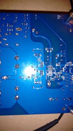
In attach photo. Let me know if it is enough...
OK
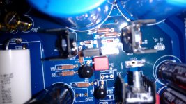
probably I found the problem I have inverted db139 and bd 140...
I'm happy that you found the problem. 🙂
Replace also both zeners and it's not a bad idea to replace also the LM317s.
LM318 and LM3886 should not be affected.
Replace also both zeners and it's not a bad idea to replace also the LM317s.
LM318 and LM3886 should not be affected.
My build will stop again, I'm being in Milan and Turin till next Wednesday. I managed to solder Amtrans on one side - too late for asking, but if C32 goes reversed, printed side of Amtrans' goes on same side, right? Wish I'd have taken a picture...
My soldering struggle is still on, seems my iron suffers working at high temperature and sometimes it "misses it", while the wire I'm using needs it really. Hope I haven't burnt the Amtrans...!
So, I'll order 50g of Oyaden, just found a cheap eBay seller from Spain.
Inviato dal mio D5803 utilizzando Tapatalk
- Home
- Amplifiers
- Chip Amps
- My_Ref Fremen Edition - Build thread and tutorial