Those readings sound reasonable i.e. the voltage across TR09 is adjusting with the preset, and importantly when you reach around 3.7 volts the bulb lights showing the output stage is drawing current. That's all good.
What's not good is the 14.86 on the collector and the 12.4 on the emitter because those voltages are creating your offset error problem. You'll find in the good channel that the voltages are more likely to be a small positive voltage on the collector and a small negative on the emitter.
So the question is where is the error occurring. Is the DC offset preset wiper still grounded as we had before ?
No But as soon as I earthed the offset trimmer wiper to chassis the amp came out of protection! TR09 Collector now reads 1.72v and Emitter reads -2v.
Last edited:
Right then 🙂
So this keeps taking us back to a problem around the trimmer and its diodes (or the print around there).
So this keeps taking us back to a problem around the trimmer and its diodes (or the print around there).
Ive taken the trimmer out and tested it and replaced the 2 diodes although they tested OK? Ill check the tracks and solder joints back to R01 ground?
The voltage on each diode should be rock solid at approx +600mv with two providing a -/+0.6 volt supply that the trimmer connects across.
Just measure the voltage on each diode leg (including ground as a confirmation it really is at zero) and check the voltages do not vary.
When the preset is all coupled up and the amp running, whatever voltage you set on the wiper should hold... and that voltage is what you are feeding to the amp input to null the basic offset error to zero.
Grounding the wiper and finding the amp is OK is proof enough the problem is just around the preset.
D02 and D04 are both a steady .628v!Measured across the pins. D02 at the trimmer end to ground is .083v the other end is .536v. D04 at the trimmer end is 1.16v and the other end is .530v to .545v with it jumping about.Ill try and find why the wiper isnt getting to ground but it sure isnt obvious? Its 3am so Ill have a good look at it in the morning.Thanks Mooly your help and patience is much appreciated.
The steady diode voltage is good. Now make sure that the junction of the diodes really is 0.00 volts (because the diode junction connects to ground).
The preset connects across these two diode... look at the circuit 🙂
This means that the wiper should be smoothly adjustable from +0.628 volts down to zero, and then continuing on to -0.628 volts.
Shorting the wiper as we have done simply places a fixed known voltage of 0.00 volts on the input of the amp. When you remove that short, you should be able to set the wiper to any voltage between +0.628 and -0.628.
If you set the wiper voltage to 0.00 then the amp should work just the same as when the short was in place. It has to 🙂
Go through the steps and check the voltages along the way.
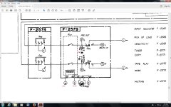
The green light doesnt come on anymore!The redlight turns on at power up but turns off when the relay is supposed to cut in? The LED reads 1.5v one way and 1.8v the other way on my DMM diode setting. I took the pre amp/power amp switch off and found an earth wire broken on the left channel. So that sounds like the wiper earth problem? Ive checked out the reg/protect board F-2568 but cant find anything wrong there except for D03,it read a bit low so I changed it for a 1N4148. D01,1N60 has a forward voltage of .380v.Ive marked the voltages in the schematic. I think M pin 38 was 1v before instead of the .244v now! Thats if I remember correctly? X marks the spot where the earth wire broke off. It might be an oxidised wire at the switch connection thats causeing this so Ill change them. (theres a few wires there) Once I find this green light problem its fixed.lol😀
Attachments
Last edited:
So this is a totally different issue we are talking about now ? The power amps are OK and all is working apart from the LED ?
Yay! I just had a look and found it! It was a cracked track on the power supply F-2567 near the relay. Ill put the amp back together tomorrow and bias it and let you know how I go Mooly,it looks to me that its fixed but you never know. lol 😀So this is a totally different issue we are talking about now ? The power amps are OK and all is working apart from the LED ?
Attachments
Excellent, well done 🙂 Those are classic hard to find faults. Let us hope that is the final fault.
Murphys law strikes again! I set the DC offset on both channels. Then the left channel bias to 50ma. Remember the right channel wouldnt bias past 18ma? That fault is still there, it goes up to 22ma at full anticlockwise on the bias trimmer? With the driver board plugged into the output modules,all of the outputs transistors emitters read shorted at .077v for PNP and .080 to .090v for NPNs. All except for the PNP transistors on the right channel,they read normally as if not plugged in? I think if I remember correctly the emitters should all read shorted,I could be wrong though?
Most important question. Does the amp actually work OK ?
The low bias is easily corrected as long as the basic amp is OK. If the offset adjusts, and the bias adjusts (albeit not to the recommended value), and the amp plays music OK... then we can sort the bias by altering a single resistor around TR09/10.
The low bias is easily corrected as long as the basic amp is OK. If the offset adjusts, and the bias adjusts (albeit not to the recommended value), and the amp plays music OK... then we can sort the bias by altering a single resistor around TR09/10.
Yes the amp is working its just that the right channel is obviously not as loud! Theres hardly any bass on the right channel?
Last edited:
The bias adjustment will have no effect on gain.
Firstly, a genuine lack of bass can only be down to a faulty (or incorrect fitted value) capacitor in the signal path, or, and this is unlikely, an incorrect value resistor following a coupling cap.
So you need to be 100% sure this bass problem is power amp related, and not in the preamp front end. For the power amp it can only be either C01/C02 or C07/C08. The later one is marked BP or bipolar. You can use a standard electrolytic here as the DC voltage will be very small. Ideally measure the few millivolts present across the cap and fit the replacement to match the measured polarity.
Low gain. Again you need to be sure this is power amp related. The only components that set the gain are R23/24 and R21/22.
An incorrect component value around the power amp input stage could give this fault. That's all the parts to the left of TR01/TR02. Just make sure they are the correct values.
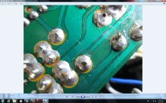
The resistors and capacitors are the right values and read spot on. I found a collector wire from the connector plug to the right PNP output board hanging by a thread so I resoldered it on. The right channel sounds a bit better but its still pretty feeble.Its the constant movement from taking the driver board in and out all the time that breaks them. I noticed that the left channel was reading 10ma when I had set it to 50ma yesterday? So I set it to 20ma to match the right side. Then I find the DC offset has gone from under 1 ohm to 320 ohms on the right side,I set it back to under 1 ohm and the next time I turned it on it was -280 ohms! I was adjusting it again when it jumped back to 320 ohms? I resoldered the trimmer pins etc and I was listening to the left channel,as I turned the volume up to half way the DBT came on at full brightness. Its more than likely another broken wire somewhere,Ill sleep on it and find it tomorrow, its 1.30 now so I think Ill have an early night.
OK, and (lol 😀) it sounds like you need a break from it for a while. You seem to get a different symptom every time you come back to it.
The bulb will light as the volume goes up, that's absolutely normal and you shouldn't really play it loud with a bulb in place because any loud bits in the music can cause the rails to suddenly collapse.
The bulb will light as the volume goes up, that's absolutely normal and you shouldn't really play it loud with a bulb in place because any loud bits in the music can cause the rails to suddenly collapse.
Just a comment - As Mooly suggests, you will flatten the power supply with every audio peak, if you are trying to play through speakers whilst a lightbulb limiter is fitted. Meter the rails with a 'scope and see.Yes the amp is working its just that the right channel is obviously not as loud! Theres hardly any bass on the right channel?
I have puzzled over a similar test problem and it seems the stereo channels don't share current equally at very low supply voltage. One channel does seem to go soft whilst the other continues to a somewhat higher output level, perhaps as you find.
If you have a larger bulb (try a PAR38 outdoor bulb or 2 in parallel if you can't find a standard incandescent type of sufficient power) you will soon see if this is the weakness problem. Alternatively, test one channel at a time or simply don't load test it yet - just test with headphones, with a scope etc. and avoid power issues until you are certain everything else is in order.
OK, and (lol 😀) it sounds like you need a break from it for a while. You seem to get a different symptom every time you come back to it.
The bulb will light as the volume goes up, that's absolutely normal and you shouldn't really play it loud with a bulb in place because any loud bits in the music can cause the rails to suddenly collapse.
The bulb wasnt lighting up as the volume was turned up! Thats what I was checking out when the bulb went fully lit, I turned it down but it stayed lit so I hit the power switch.Ive found another fault but it didnt fix the main problem it was a broken clip inside the right channel posistor plug. it had started the relay machine gunning. Anyway Ill find this main problem,theres no doubt about that. lol😀
Ive replaced all the flaky worn out wiring that I could find and there was lots of it. lol Ive set the DC offset on both channels to under 1 ohm. Both bias trimmers still arent working properly,they have -1.6v on the right channel bias trimmer wiper and -1.5v on the left one. The bias goes up but at a very slow rate,about three full turns for 1ma? Seeing as both channels are affected do you think the problem could be on the Volume buffer board? F-2574 seeing as the DBT lit up fully before when I turned the volume up and the trimmers were turned full on to get approx 20ma on the left channel and about 10ma I think it was on the right channel? The DBT isnt lighting up as I turn the bias trimmers now,its just a low orange glow.Can I bias the amp with the pre-amp disconnected?
- Status
- Not open for further replies.
- Home
- Amplifiers
- Solid State
- 47 volts on output resistors?