Hello,
My father and I are re-building a Williamson amplifier that he originally made in the UK in the early 1950s. It was used for about 15 years, undergoing many repairs along the way, and has been in storage ever since with most of the valves now broken or missing. For quite some time we've been wanting to restore it and get it running again, and we've finally started.
I thought I'd document the progress here, in the hope that I can get some assistance with the re-build. I've sourced most of the parts we need, but as I start to do the wiring many questions are coming up.
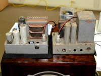
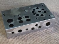
It was originally built in two sections, the power supply is on a tin plated steel chassis with the plates soldered together, and the amplifier is on a folded aluminium chassis with 3/8" square aluminium blocks screwed in the vertical corners.
The amp was built to the "new version" circuit diagram as published in Wireless World in 1949 and uses 2 x KT66 valves. The power supply used a U52 rectifier (from the original 1947 design) but we'll be replacing this with an indirectly heated 5V4 to bring the power supply up to the 1949 spec. This is the only planned significant departure from the original as-built spec.
Graham.
My father and I are re-building a Williamson amplifier that he originally made in the UK in the early 1950s. It was used for about 15 years, undergoing many repairs along the way, and has been in storage ever since with most of the valves now broken or missing. For quite some time we've been wanting to restore it and get it running again, and we've finally started.
I thought I'd document the progress here, in the hope that I can get some assistance with the re-build. I've sourced most of the parts we need, but as I start to do the wiring many questions are coming up.
It was originally built in two sections, the power supply is on a tin plated steel chassis with the plates soldered together, and the amplifier is on a folded aluminium chassis with 3/8" square aluminium blocks screwed in the vertical corners.
The amp was built to the "new version" circuit diagram as published in Wireless World in 1949 and uses 2 x KT66 valves. The power supply used a U52 rectifier (from the original 1947 design) but we'll be replacing this with an indirectly heated 5V4 to bring the power supply up to the 1949 spec. This is the only planned significant departure from the original as-built spec.
Graham.
Attachments
Last edited:
Oldvinylplayer, sounds like a fun Father Son project. Glad you are planning on sharing the journey here on DYI Audio as it will be fun to follow your progress. Hope all goes well for you and should you hit any trouble spots there is plenty of good advice available here. Have fun!
Mickeystan
Mickeystan
I've stripped all the metalwork back to bare metal, and de-rusted and re-soldered the power supply chassis. It will be spray painted in machinery grey, matching the original.
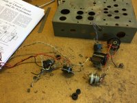
The wiring was a mess, with many heat damaged and aged wires and resistors, and the original switches looked outright dangerous, so most components will be replaced with new. We've tested the power transformer and it didn't immediately blow up, so I'll re-paint the soldered and sealed case and see if it can be re-used.
I've purchased some heater wire from a local valve amplifier part supplier. It's single strand and has a layer of PVC then cotton insulation. Can this single strand wire be twisted? Or do I need to use multi-strand to be able to safely twist all the heater wiring?
Graham.
Attachments
Can this single strand wire be twisted? Or do I need to use multi-strand to be able to safely twist all the heater wiring?
Graham.
single strand is best for this cos it stays twisted.
Have fun!
OK, thanks, so the single strand won't get overstressed by the twisting? How many twists per inch is safe?
Graham.
Graham.
OK, thanks, so the single strand won't get overstressed by the twisting? How many twists per inch is safe?
Graham.
as tight as you can reasonably wind it by hand. I usually put a pair of wires in a vice at one end, clamp the other end of the wires in the chuck of a battery drill and apply the power....
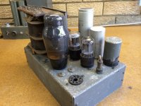
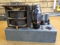
Hi Graham, I don't see a 6.3V heater winding on that power transformer??
Is there no large choke in the power supply, only the smaller choke for the earlier stage supply rails?
Also, what output transformer is that?
Do you have access to an insulation resistance meter? Well worth trying to check the performance of the transformers at 1kVDC, as well as the oil/paper cans at 500VDC.
Ciao, Tim
Hi Tim, it didn't take you long to find this thread🙂
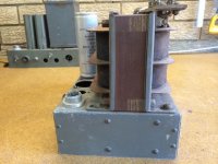
Yes, that's the smaller inductance choke (C2, 10H on the schematic) on top of the power supply chassis. The larger inductance 30H, but smaller physical size choke was mounted in the amplifier chassis, and we'll be sticking with this arrangement. The large one was an Australian Fergusson model so it's not original, and it was too large for the space on top of the chassis so I've purchased an 8H Hammond choke which fits neatly on top.
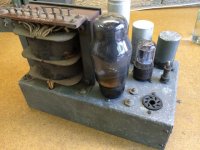
The two rectangular cans are 4uF 1000V capacitors and were C8 and C9, straddling the 10H choke. This is lower than the 8uF specified, but it's all my dad could get hold of back then. I'm not game to use any of the old capacitors, but they will all be kept for show and to block up the holes in the chassis. I'll be wiring modern electrolytics under the chassis. Any suggestions for capacitance value? Is there any benefit from going higher than the 8 uF on the schematic?
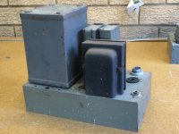
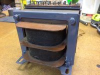
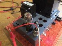
The output transformer has no brand on it. According to my dad it was some sort of kit with part of the windings done by him, but to me it looks all "factory wound". Here's a picture of it with the first coat of grey paint on the frame. I didn't want to touch the laminations with sand paper or wire brush for fear of burring their ends and altering the magnetic properties. Is this fear justified, or can I wire brush the rust off the ends of the laminations and paint them?
Yes, that's the smaller inductance choke (C2, 10H on the schematic) on top of the power supply chassis. The larger inductance 30H, but smaller physical size choke was mounted in the amplifier chassis, and we'll be sticking with this arrangement. The large one was an Australian Fergusson model so it's not original, and it was too large for the space on top of the chassis so I've purchased an 8H Hammond choke which fits neatly on top.
The two rectangular cans are 4uF 1000V capacitors and were C8 and C9, straddling the 10H choke. This is lower than the 8uF specified, but it's all my dad could get hold of back then. I'm not game to use any of the old capacitors, but they will all be kept for show and to block up the holes in the chassis. I'll be wiring modern electrolytics under the chassis. Any suggestions for capacitance value? Is there any benefit from going higher than the 8 uF on the schematic?
The output transformer has no brand on it. According to my dad it was some sort of kit with part of the windings done by him, but to me it looks all "factory wound". Here's a picture of it with the first coat of grey paint on the frame. I didn't want to touch the laminations with sand paper or wire brush for fear of burring their ends and altering the magnetic properties. Is this fear justified, or can I wire brush the rust off the ends of the laminations and paint them?
Attachments
Best to stay close to the original cap values - the power supply end values impact the valve rectifier, and all the others impact the low frequency stability performance.
Do you have a photos of the other side of the output transformer - the tappings are where all the fun is. The core clamp/mount looks solid.
There is no concern with brushing/sanding/painting the edges of laminations - old wives tales may have you worried. Try not to undo the clamps - that may cause some separation of laminations.
OK, thanks, it's good to know it's safe to clean and paint the laminations, they are in a pretty rough state.
Here's some shots of the output transformer. The cotton insulation, whilst old, does look intact, and all the copper wire is still firmly attached to the terminations.
Graham.
Here's some shots of the output transformer. The cotton insulation, whilst old, does look intact, and all the copper wire is still firmly attached to the terminations.
Graham.
Attachments
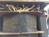
You may need a bit of heat shielding - that KT66 may have caused the insulation discolouration.
Toasty conditions on that smallish chassis!
Do the feedback wires go via the connector on the corner?
Toasty conditions on that smallish chassis!
Do the feedback wires go via the connector on the corner?
Tim,
That's a good suggestion to add some shielding. The outer insulation has cracked and is actually missing in that damaged area, but the enamelled copper windings look clean and intact. We've probably just caught it in time.
Yes, it's tight on the chassis. Makes me wonder how builders got on when building a Williamson all on one chassis.
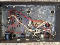
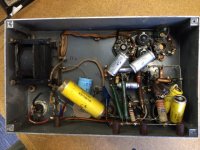
The feedback wire and resistor was under the chassis. I think it's the 47K in the photos below. As you can see, the wiring underneath is a jumble, it's a wonder my dad ever got the amp running stable and quiet 🙂 Any advice on routing of the feedback wire?
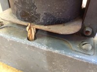
On top is the input connector, which we'll retain because we have the plug as well, and in the corner a "Plessey" 4 pin connector which carried the HT and the 6.3V from the power supply all in one cable - pretty scary! I have some questions about this HT interconnection but will take some more photos at the weekend before asking any more about this.
To answer your earlier question, at one time there was a separate 6.3V transformer under the power supply chassis, but this was missing. I've just sourced a Hammond 6.3V centre tapped 6A item, but frustratingly it's 6mm wider than their data sheet indicated. We'll need to do some chassis modifications to get it to fit, or I'll route a depression in the timber base I intend to make for the finished amplifier.
Graham.
That's a good suggestion to add some shielding. The outer insulation has cracked and is actually missing in that damaged area, but the enamelled copper windings look clean and intact. We've probably just caught it in time.
Yes, it's tight on the chassis. Makes me wonder how builders got on when building a Williamson all on one chassis.
The feedback wire and resistor was under the chassis. I think it's the 47K in the photos below. As you can see, the wiring underneath is a jumble, it's a wonder my dad ever got the amp running stable and quiet 🙂 Any advice on routing of the feedback wire?
On top is the input connector, which we'll retain because we have the plug as well, and in the corner a "Plessey" 4 pin connector which carried the HT and the 6.3V from the power supply all in one cable - pretty scary! I have some questions about this HT interconnection but will take some more photos at the weekend before asking any more about this.
To answer your earlier question, at one time there was a separate 6.3V transformer under the power supply chassis, but this was missing. I've just sourced a Hammond 6.3V centre tapped 6A item, but frustratingly it's 6mm wider than their data sheet indicated. We'll need to do some chassis modifications to get it to fit, or I'll route a depression in the timber base I intend to make for the finished amplifier.
Graham.
Attachments

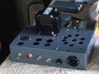
Some progress over the weekend. I've spray painted both chassis, and mounted the switches, mains inlet socket, lamp, valve sockets, choke etc. There were a couple of unused holes on the power supply front panel which have been plated behind with sheet brass, then solder filled and filed to be flush on the front. Two switch holes needed sleeving down to a smaller diameter with short sections of suitably sized steel tubing, again soldered in place and filed flush. I think the machinery grey oil-based enamel has covered these repairs up well.
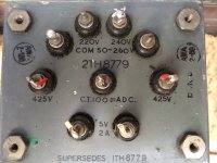
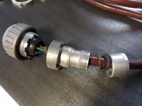
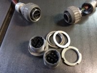
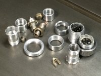
Because there are two chassis the HT and the 6.3V heater supplies were originally run between the two chassis via a 4 core cable and a 4 pin "Plessey" connector which appears to be some sort of war surplus item (see photos below).
The connector components are a little corroded and covered inside with flux residue, but will clean up with a solvent soak then buffing on a polishing mop wheel, and the crucial plastic piece supporting the pins and sockets seems intact, so I think we'll be OK re-using this connector. However, for safety I've decided to run the 6.3V heater supply via a second cable and connectors (a modern Bulgin set). If there is a HT "event" in the interconnecting cable I don't want that arcing across and getting in to the heater circuit.
What do people think of this plan? Do I just use 240V mains rated cable for the HT connecting cable?
Originally, the only earth connection between the two chassis was the -ve of the HT supply. Should I run a separate earth connection through the cable and connectors, or maybe make a separate earth strap? Or is this just risking earth loop problems?
Any advice is welcome.
Graham.
Attachments
If it were an industrial device, then the mains protective earthed power supply chassis would use a fixed earth connection to the other amp chassis. You can then have one fixed link connection from amp 0V to amp chassis - that leaves the B+ supply floating in the power supply chassis if the connector is removed - which could be managed by having the B+ ground in the power supply chassis grounded via say a 'ground lifter' circuit such as back-to-back diodes.
Unless you have better wire available, then mains rated cable is a good compromise.
Unless you have better wire available, then mains rated cable is a good compromise.
Thanks Tim,
You've just made me realise that with the current plan I'd lose the earth to the amp chassis when the HT connector is not connected. So there could be a circumstance that heater power is being fed to the amp chassis from the heater transformer in the power supply chassis, yet the amp chassis is not earthed. This sounds like a no-no to me.
I could solve this by running a chassis earth in both HT and heater cables, this way if there is high voltage or low voltage power to the amp there would always be a path from the chassis back to mains earth. Or I could add a separate, hard wired earth strap between the two chassis.
I don't understand what you are saying in your comment about the B+ supply being left floating. Does it matter for safety if 0V in the PS is not earthed?
As an alternative,could I add a separate earth strap between the two chassis (or run chassis earth wires in both HT and 6.3V connector cables), and tie the incoming mains earth lead to the PS chassis in one place. This would ensure that all exposed metal is always earthed. Then tie PS 0V to chassis at one place in the PS? In this scheme, the 0V rail in the amplifier chassis would not be tied to the chassis there.
Graham.
The signal 0V is preferably connected to chassis at one point only. As a preamp would be connected to amp, then better to make that link in the amp chassis.
The protective earth connection is preferably fixed, and not via an umbilical connector. The connection is from chassis to chassis. Using a removable lead with protective earth needs more consideration from a safety perspective - one consideration we easily see is that the earth pin is longer than the active/neutral in aussie mains 3-pin plugs.
If the above two recommendations are followed, then there is no link in the power supply chassis from PE to B+ 0V (as that link is made over in the amp chassis). So if the umbilical was disconnected, and the power supply turned on, then the B+ supply would be floating - which is typically a more hazardous situation than if it was grounded.
OK, thanks Tim, I'd overlooked the input signal connection.
But I'm still not understanding this part. How can the B+ 0V or 450V be taken any higher than they are?
You've probably guessed that I'm not an electronics engineer 🙂
Graham.
then the B+ supply would be floating - which is typically a more hazardous situation than if it was grounded.
But I'm still not understanding this part. How can the B+ 0V or 450V be taken any higher than they are?
You've probably guessed that I'm not an electronics engineer 🙂
Graham.
Last edited:
Worst case fault is probably mains active touching (or insulation fails through to) a PT secondary circuit, and someone touches part of that secondary circuit when another part of their body is also earthed. The peak voltage across the person could be mains peak plus B+ peak.
More progress
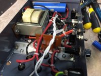
We completed the power supply over the weekend, and ran it briefly with no load to check that everything worked OK. The power transformer is 425-0-425, and we got 635V DC with no load, so that looks about right. We didn't leave it running for long because the first electrolytic before the choke is only rated at 600V.
It's tight under the PS chassis with the larger 6A heater transformer, and the 20uF electrolytic squeezed in there so it was a struggle to keep the wiring neat but I'm happy with the end result and it's certainly a lot neater than it was originally. I made a bakelite support bracket to separate the 425VAC and 5VAC wires from other wiring. I'll thread some waxed cotton through the holes to secure the wires when I'm happy that everything else is in the right place.
We also got the 4 pin Plessey HT connectors cleaned up and polished. The polishing (on a denim buffing wheel) has taken the military khaki colour off the ribbed retaining ring, so I need to think about whether to replace that finish. The original colour was pretty thin and may have been anodising, and I'm not sure that paint would look right.
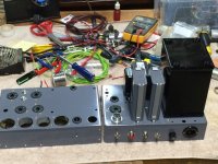
We also got all the hardware mounted on the amplifier chassis. We'll start the point to point wiring and small component fitting next.
As always, I'd welcome any comments or advice on the project as we go along. How does the wiring look? That cotton covered wire is a pain to work with, and does not like twisting at all! I could not use the normal electric drill technique and had to twist it by hand with the straight ends of the wire free to rotate.
Graham.
We completed the power supply over the weekend, and ran it briefly with no load to check that everything worked OK. The power transformer is 425-0-425, and we got 635V DC with no load, so that looks about right. We didn't leave it running for long because the first electrolytic before the choke is only rated at 600V.
It's tight under the PS chassis with the larger 6A heater transformer, and the 20uF electrolytic squeezed in there so it was a struggle to keep the wiring neat but I'm happy with the end result and it's certainly a lot neater than it was originally. I made a bakelite support bracket to separate the 425VAC and 5VAC wires from other wiring. I'll thread some waxed cotton through the holes to secure the wires when I'm happy that everything else is in the right place.
We also got the 4 pin Plessey HT connectors cleaned up and polished. The polishing (on a denim buffing wheel) has taken the military khaki colour off the ribbed retaining ring, so I need to think about whether to replace that finish. The original colour was pretty thin and may have been anodising, and I'm not sure that paint would look right.
We also got all the hardware mounted on the amplifier chassis. We'll start the point to point wiring and small component fitting next.
As always, I'd welcome any comments or advice on the project as we go along. How does the wiring look? That cotton covered wire is a pain to work with, and does not like twisting at all! I could not use the normal electric drill technique and had to twist it by hand with the straight ends of the wire free to rotate.
Graham.
Attachments

- Status
- Not open for further replies.
- Home
- Amplifiers
- Tubes / Valves
- Williamson amplifier re-build