It seemed like common sense using my signal generator and a Kelvin connection, you're just measuring impedance after all. I mainly want at least 5nH resolution. However it is not portable. I would be surprised if someone has not worked out how to make useful measurements in an inexpensive dedicated device.
How you avoid the test current mucking up the result is very important and very tricky.
Also, how you zero the measurement apparatus is also important.
HP had some really great writeups on all of that.
Anybody who wants to try this, I will be glad to assist.
John
JN
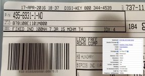
The table Mark so nicely cleaned up is from the AC line. The rest was responding to another issue.
The table Mark so nicely cleaned up is from the AC line. The rest was responding to another issue.
Not the optimum experiment but at least it yielded some actual data. Be sure to click on the left image to see it full size; this allows you to read the tolerance from the table.
Thanks.
Repeat the test with the exact same layout, but this time while the measurement is on, short directly across the measurement terminals. The meter will display the test zeroing error. Subtract that shorted number from the meter reading of the unit. (lock the range if it autoranges)
The tolerance is a combination of winding geometry control, permeability variation of the core, lead dress control, and meter control by the vendor.
For winding geometry on an air core coil, we typically use 4% as the manufacturing tolerance. Resistance at 2%.
When the core dominates, and at low nH, parasitics come into play as well, also lead dress.
John
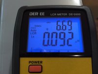
ps..I really like that meter. What test frequencies can it do?
Last edited:
Since I'm a very enthusiastic user of Neil Heckt's "AADE LC Meter II"
I'm already quite familiar with the null-out-the-fixture-parasitics-before-measuring protocol. The AADE LC Meter II forces you to do this and, after you make a couple hundred inductance measurements, eventually it becomes second nature. However Neil passed away recently and he stopped selling kits & fully assembled meters when he died. So I can't really recommend that member keantoken should get one of them. Hence this one; second best but available.
The DE-5000 has a similar procedure; see the English language user manual pp. 15-17 or the Chinese language manual pp. 9-10. I ran this procedure before taking the measurement shown here in #83262, so there is no further data adjustment to perform.
me too, mark. very nice device.
too bad they're not selling them anymore.
i didn't know he passed; he was a nice guy from my exchanges with him.
mlloyd1
too bad they're not selling them anymore.
i didn't know he passed; he was a nice guy from my exchanges with him.
mlloyd1
With the full circuit diagram, one can restart the site under new managment ot just make it yourself from the circuit and pcb layouts shown or your own pcb layout.
lc meter project kit
THx-RNMarsh
lc meter project kit
THx-RNMarsh
Yes a smaller amount is detectable, but that does not invalidate the observation (!) that with a < 30dB channel separation systems excellent sound stage and image positioning can be obtained. That however DOES invalidate the view that you need very high channel separation to get good soundstage and positioning.
The remaining question then becomes: why do we need such very high channel separation figures anyway??
Jan
It isnt that you cant get some plesent stereo sound stage from 10, 20 or 30dB channel seperation. It is about an accurate sound stage without loss of info cancelled out by the low x-talk.
When you do my experiemnt, you can determine what the string length is for your system. You might not hear any further change as the x-talk is reduced.... that would be your channel sep or x-talk number needed.... greater will have no affect.
Also noted is that speakers with wide dispersion vs narrow dispersion will have a Big impact on that number. However as a design issue, you would have the highest channel separation for all conditions to get best results everywhere.
THx-RNMarsh
Last edited:
And how will you program the ROM of integrated circuit "U2" in the schematic you linked? It's got the security bit enabled so you can't simply download the bits from a preexisting, golden LC meter II device, assuming you could find one.With the full circuit diagram, one can restart the site under new managment ot just make it yourself from the circuit and pcb layouts shown or your own pcb layout.
lc meter project kit
THx-RNMarsh
You did not give this very much thought, did you?
Did you try to contact the person there (spouse, son, daughter).... and ask if there are any of those parts or information laying about. ETC. Ask for what you need. Then, if you can't get one that way, you are SOL.
THx-RNMarsh
THx-RNMarsh
Last edited:
Did you try to contact the person there (spouse, son, daughter).... and ask if there are any of those parts or information laying about. ETC. Ask for what you need. Then, if you can't get one that way, you are SOL.
THx-RNMarsh
Whom are you saying this to?
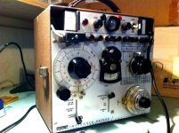
this old school approach may be of interest to some. it has the advantage of being able to take an external oscillator input, in addition to the fixed internal one. shown is the ESI Impedance Bridge Model 250 DA, which is aka and very similar to the AN/URM-90-G (made by ESI). I've got one of both, found at hamfests and have been very good to have around, rather surprisingly accurate as well. often found inexpensively too...
(stock photo, not my unit...)
(stock photo, not my unit...)
Attachments
I was considering getting one of those. Conrad Hoffman shows they can be useful for lots of things, and signal input is a very useful feature too. Just not sure how to choose a good one.
Both ESI and General Radio built a number of precision bridges like the ESI. They are usually accurate or broken. Switch contacts will be the most likely to need cleaning. They are all old. Measuring larger inductors can be challenging with one of those. GR made several bridges specifically for bigger inductors. For small inductors there are some instruments from HP/Boonton that work better if you are interested in the vintage solutions.
I use an ESI Videobridge which works great but the price on these has gone up considreably from the $100 or so I paid. The DER looks really nice.
I use an ESI Videobridge which works great but the price on these has gone up considreably from the $100 or so I paid. The DER looks really nice.
Wurth Electronics is offering me either a complimentary mug or a golf towel. Which would you choose?
Wurth Electronics is offering me either a complimentary mug or a golf towel. Which would you choose?
A golf towel isn't too much help for your morning coffee I guess 😉
BTW had a visit to one of the worlds' largest record pressing plants in the world, Record Industry in Haarlem, The Netherlands.
Aside from the absolutely fascinating processes involved, one thing struck me, when the mastering engineer said: 'You know, we get the master files, either digital or a tape, and then I listen to them, and add a bit base or some presence, maybe dim too bright highs until it sounds right to me, before I cut it."
He did say that normally he checked back with the customer if they agree to his changes, but it puts the effort of the recording engineer in a different perspective.
Jan
add a bit base or some presence.....before I cut it
Some parts read familiar.
Makes one wonder whether the recording engineer is informed, or on a not need to know base.
Well you know how it is, they play the original, then do something to it and presto! it sounds more enjoyable (which some still call, by lack of better understanding, 'better').
Maybe we should consider the final product coming out of the recording studio a basic template to which we can apply our personal manipulation to make it sound the way WE like best.
Why should ANY recording engineer determine how MY music should sound??
The QUAD 44 was absolutely brilliantly conceived but we have let ourselves be led astray by the this-is-what-it-must-sound-like crowd, taking away even a basic loudness adjustment. Helpless consumers we became.
Jan
- Status
- Not open for further replies.
- Home
- Member Areas
- The Lounge
- John Curl's Blowtorch preamplifier part II