Yes, TBTL suggested the standing wave. The horn is 34cm long (axially), equating to a 1/2 wavelength for 500Hz...sort of close enough to the center of the dip in the first measurement (at 450Hz). And the explanation for the change in frequency in the 2nd measurement would be the coffee table acting as an extension to the mouth.
What causes the standing wave?
What causes the standing wave?
- Does the reduced throat by the white piece influence this?
- The abrupt 90° edges of the MDF top/bottom plates? Might rounding these help?
- My guess is the vertical sides aren't the biggest culprits since they expand per a tractrix.
I suppose you could call it an impedance mis-match between the mouth and the free space surrounding it. Maximum power is transferred between two like impedances (just as with electronics).
The difference is isolated at that point. This wayward energy behaves as if the mouth is its source and some heads back to the throat.
2. Yes I'd expect this to change a standing wave issue. A roundover would have to be reasonably sized to deal with these frequencies, but the middle of the top and bottom panels are the shortest path out of the horn regardless.
3. Probably yes.
The difference is isolated at that point. This wayward energy behaves as if the mouth is its source and some heads back to the throat.
1. Probably not significantly.
- Does the reduced throat by the white piece influence this?
- The abrupt 90° edges of the MDF top/bottom plates? Might rounding these help?
- My guess is the vertical sides aren't the biggest culprits since they expand per a tractrix.
2. Yes I'd expect this to change a standing wave issue. A roundover would have to be reasonably sized to deal with these frequencies, but the middle of the top and bottom panels are the shortest path out of the horn regardless.
3. Probably yes.
2. Yes I'd expect this to change a standing wave issue. A roundover would have to be reasonably sized to deal with these frequencies, but the middle of the top and bottom panels are the shortest path out of the horn regardless.
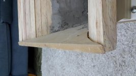
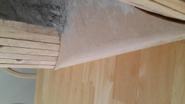
I rounded the edges. Not sure if it can be fully appreciated in the pictures.
Attachments
Lewinski,
If you just want to see what a large radius would do use some easily shaped styrofoam board or some foam core board.
If you just want to see what a large radius would do use some easily shaped styrofoam board or some foam core board.
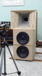
I did a fair amount of measurements today. The setup was always the same one, as seen on the picture. Everything measured on axis at 1m, with the horn always in the same position.
Variables tried today:
- Rounded edges on the top and bottom plates.
- Spacers between the driver and mounting flange, per Bruce Edgar's Midrange Horn article from '86. I tried 1/4" and 1/2" spacers.
- Foam fitted into the space generated by the spacers, also per Bruce Edgar's article.
- Dustcap glued onto the cone, with the goal of extending the top range reach.
- Rear chamber on and filled with fiberglass, or open and empty. All measurements done to date were with the chamber on and filled with fiberglass.
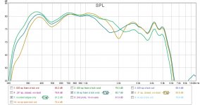
Interestingly, the dip around 480Hz is always there. Frustrating! Per the article by Bruce Edgar I was hoping it might be mitigated by the use of spacers and foam.
Showing all the measurements together is messy, so I'll do my best to display results in an orderly fashion.
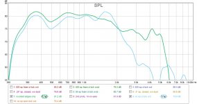
First off, same horn with the rounded edges vs previous horn with edges at 90 degrees. Basically no impact in terms of the hypothesis of the standing wave being formed by the sharp edges. Maybe something else is causing the dip?
All other measurements were done with the rounded edges in place.
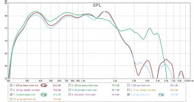
Next is the measurement with rounded edges (for reference, as my starting point today) vs 1/4" spacers vs 1/4" spacers plus foam. Always with back chamber on. Adding the spacers worsened things with a pronounce dip at 2kHz. Adding the foam actually improved things.
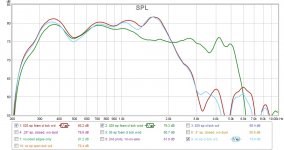
Third chart is rounded edges vs 1/2" spacers vs 1/2" spacer plus foam. Things worsened vs 1/4" spacers.
Fourth is vs the driver with dustcap on. The top end was raised, but the mass rolloff worsened as a consequence of the added mass, I think.
Fifth is vs driver with dustcap and 1/4" spacer with foam.
The last one has the ones I think look best. The dip around 480Hz is an issue, though.
What do you think?
Variables tried today:
- Rounded edges on the top and bottom plates.
- Spacers between the driver and mounting flange, per Bruce Edgar's Midrange Horn article from '86. I tried 1/4" and 1/2" spacers.
- Foam fitted into the space generated by the spacers, also per Bruce Edgar's article.
- Dustcap glued onto the cone, with the goal of extending the top range reach.
- Rear chamber on and filled with fiberglass, or open and empty. All measurements done to date were with the chamber on and filled with fiberglass.
Interestingly, the dip around 480Hz is always there. Frustrating! Per the article by Bruce Edgar I was hoping it might be mitigated by the use of spacers and foam.
Showing all the measurements together is messy, so I'll do my best to display results in an orderly fashion.
First off, same horn with the rounded edges vs previous horn with edges at 90 degrees. Basically no impact in terms of the hypothesis of the standing wave being formed by the sharp edges. Maybe something else is causing the dip?
All other measurements were done with the rounded edges in place.
Next is the measurement with rounded edges (for reference, as my starting point today) vs 1/4" spacers vs 1/4" spacers plus foam. Always with back chamber on. Adding the spacers worsened things with a pronounce dip at 2kHz. Adding the foam actually improved things.
Third chart is rounded edges vs 1/2" spacers vs 1/2" spacer plus foam. Things worsened vs 1/4" spacers.
Fourth is vs the driver with dustcap on. The top end was raised, but the mass rolloff worsened as a consequence of the added mass, I think.
Fifth is vs driver with dustcap and 1/4" spacer with foam.
The last one has the ones I think look best. The dip around 480Hz is an issue, though.
What do you think?
Attachments
-
 20160625_190940_resized.jpg420.4 KB · Views: 295
 -
 wood horn without dustcap with sharp vs rounded edges.jpg103 KB · Views: 279
 -
 wood horn without dustcap rounded edges vs 025 space vs 025 sp with foam.jpg108.4 KB · Views: 258
 -
 wood horn without dustcap rounded edges vs 05 space vs 05 sp with foam.jpg109.8 KB · Views: 104
 -
 wood horn without dustcap vs with dustcap.jpg100.1 KB · Views: 95
 -
 wood horn without dustcap rounded edges vs no spacer with dutcap vs 025 sp with foam with dustca.jpg109.9 KB · Views: 101
 -
 promising.jpg111.3 KB · Views: 107
the middle of the top and bottom panels are the shortest path out of the horn
A pronounced effect may be implying a lack of supporting mouth size, which hasn't really changed due to this roundover. A quarter wavelength at 480Hz makes for a much larger roundover, and the idea of trying substantial temporary baffling was to try to get some response to the issue.same horn with the rounded edges vs previous horn with edges at 90 degrees. Basically no impact in terms of the hypothesis of the standing wave being formed by the sharp edges.
I think that higher frequency response is a different matter. Even though there is enough supporting mouth at higher frequencies and it shouldn't be as necessary for a significant response change, these are more sensitive frequencies and it doesn't take as much of a disturbance to be heard, so a small roundover like you have does have its benefits but I wouldn't expect much at the dip.
Reduce the size of the rear enclosure, not by stuffing with fiberglass but put something solid inside that takes up most of the room and let's see if you extend the bottom end, I suspect you will be surprised. Make it as small as possible.The only reason to add a spacer between the back of the horn and the driver is so the cone or surround doesn't hit the back of the horn. With the foam and a spacer you are just creating a leak into the rear chamber and causing some cancellation.
Last edited:
A pronounced effect may be implying a lack of supporting mouth size, which hasn't really changed due to this roundover.
I was thinking along the same lines: the size of the WL at 480Hz is not really comparable to the roundover on the top/bottom. Mouth size could be. Can you think of any way to prove/disprove the hypothesis, short of building another horn?
In my mind the dip is being caused by the horn itself. Pointing the setup up kept the dip there. Modifying what is around the driver and out of the horn didn't affect it.
It is also clear to me the dip at 480hz and the top end are caused by different aspects.
Reduce the size of the rear enclosure, not by stuffing with fiberglass but put something solid inside that takes up most of the room and let's see if you extend the bottom end, I suspect you will be surprised. Make it as small as possible.
I've been meaning to do this but haven't because I haven't figured out how to use REW to measure impendance and hence adjust the peak to where I want it. I guess I could still take a shot.
But are you expecting lower reach or reduced dip at 480Hz? As it stands the reach seems good for my goals: I intend to xo at 400Hz and the horn was designed with fc of 200Hz and by 300hz it is already up there. So lowering reach wouldn't be a goal in itself. Reducing the dip, on the other hand, would.
I'll try a bag of sand for a quick n´dirty shot. During the week I'll try to get closed cell expanding/hardening foam.
The way I built mine, the leak goes into the room, not the back chamber. Without the spacers the cone/dustcap wasn't hitting the back of the horn (I built it so it didn't).The only reason to add a spacer between the back of the horn and the driver is so the cone or surround doesn't hit the back of the horn. With the foam and a spacer you are just creating a leak into the rear chamber and causing some cancellation.
By the way, am I getting too worked out with the vertical axis, influenced by the scale I adopted? The last chart on #165 shows 2 setups that are +/- 3dB from 350Hz to 2kHz, and one from 350Hz to 3kHz.
How good is good enough? Of course I would love +/- 1dB, but is it realistic?
This question should be answered from experience, which I don't have and you do 🙂
How good is good enough? Of course I would love +/- 1dB, but is it realistic?
This question should be answered from experience, which I don't have and you do 🙂
Lewinsky,
You need to remember that most horns are designed with a target length that supports 1/4 wavelength of the low frequency target. So there is always a reversion wave happening, that is a given with a finite horn length. You also have to look at the width and height when the horn is not symmetric around the axis for other modes. So all the theoretical programs are in fact just approximations and are often not correct. I don't know what the FR of your diver is before loading into the horn. There are many variables going on here. There is more than just increasing the low frequency response as regards to the rear chamber there is also reactive loads to consider and impedance matching to the mouths impedance. I'll just repeat that to my eyes alone that is a huge rear chamber for a short midrange horn, I don't think it is doing you any good at all. Take it off completely and see what you get and then reduce the size to a very small size and look at how the rear chamber affects the FR. Compare the three different situations, what you have now, no rear chamber and a very small rear chamber and you will start to see how the rear air loading is affecting the on axis output. Designing horn lenses is not as simple as it would seem, the shape changes have much more effect than many realize, that is at least as important as the flare type you use, whether exponential, hyperbolic, hypex or oblate spheroid. This is truly a very complex system with many interdependent relationships. Planar wave concepts are flawed simplistic ways of looking at at any type of waveguide, just my two cents worth of thinking for today.
You need to remember that most horns are designed with a target length that supports 1/4 wavelength of the low frequency target. So there is always a reversion wave happening, that is a given with a finite horn length. You also have to look at the width and height when the horn is not symmetric around the axis for other modes. So all the theoretical programs are in fact just approximations and are often not correct. I don't know what the FR of your diver is before loading into the horn. There are many variables going on here. There is more than just increasing the low frequency response as regards to the rear chamber there is also reactive loads to consider and impedance matching to the mouths impedance. I'll just repeat that to my eyes alone that is a huge rear chamber for a short midrange horn, I don't think it is doing you any good at all. Take it off completely and see what you get and then reduce the size to a very small size and look at how the rear chamber affects the FR. Compare the three different situations, what you have now, no rear chamber and a very small rear chamber and you will start to see how the rear air loading is affecting the on axis output. Designing horn lenses is not as simple as it would seem, the shape changes have much more effect than many realize, that is at least as important as the flare type you use, whether exponential, hyperbolic, hypex or oblate spheroid. This is truly a very complex system with many interdependent relationships. Planar wave concepts are flawed simplistic ways of looking at at any type of waveguide, just my two cents worth of thinking for today.
Say you had the output of your sound card connected to a 1k (could use less if noise is a problem) resistor in series with 10 ohm. The input is taken across the 10 ohm resistor. Sweep level is adjusted to get 10 of something on the plot for example, and make sure the response is flat.measure impendance
Substitute the speaker for the 10 ohm resistor. Accuracy is probably important if you plan to use this for sims, but not really for this tuning excercise.
This was suggested to temporarily make the horn longer and make the mouth larger obviating a roundoverI was thinking along the same lines: the size of the WL at 480Hz is not really comparable to the roundover on the top/bottom. Mouth size could be. Can you think of any way to prove/disprove the hypothesis, short of building another horn?
what if you rest the bottom panel on the floor so the horn leans back and upturn the coffee table over the top panel?
There is more than just increasing the low frequency response as regards to the rear chamber there is also reactive loads to consider and impedance matching to the mouths impedance. I'll just repeat that to my eyes alone that is a huge rear chamber for a short midrange horn, I don't think it is doing you any good at all. Take it off completely and see what you get and then reduce the size to a very small size and look at how the rear chamber affects the FR. Compare the three different situations, what you have now, no rear chamber and a very small rear chamber and you will start to see how the rear air loading is affecting the on axis output.
I did the comparisons you suggested:
1) As it was all along, meaning the chamber filled with fiberglass and compressed to some extent.
2) Open back, meaning the PVC pipe is still there because it's glued, but it's empty and the back cover is off.
3) Rear chamber filled with sand (in a ziplock bag). It fits pretty snug so the remaining space has got to be small.
See the chart. Dip is still there. It was mainly affected by going open back. Reducing the rear chamber size with sand increased the sensitivity in the lower end, although he low end reach is still the same.
My takeaways would be the rear chamber is indeed too large and has to be reduced. Open back seems a bad idea with this horn.
Designing horn lenses is not as simple as it would seem, the shape changes have much more effect than many realize, that is at least as important as the flare type you use, whether exponential, hyperbolic, hypex or oblate spheroid. This is truly a very complex system with many interdependent relationships. Planar wave concepts are flawed simplistic ways of looking at at any type of waveguide, just my two cents worth of thinking for today.
By horn lens do you mean the dustcap?
Attachments

The Iwata horn terminated in à baffle with felt covered slots in it. Probably to make the termination of the horn gradual. As soon as I have the possibility I Will measure My horns not Only in amplitude but also in time domain.
Back when I was narrowing down which horn types to consider I was told the Iwata wasn't well suited for these frequencies. Going that route would be a radical departure from the path I'm following, and I'd rather pursue this further before quitting.
Lewinski,
I just went back and looked at your post #1 to see where this all started. A couple of things from that post. Since you originally say you will use a dsp for FR correction and phase correction I don't really see a big problem with the FR you are getting now with I would think no EQ. I am not sure why you are needing to go as low in frequency as you are with a mid horn, I would normally go higher with anything from a 15" bass driver and smaller.
What I am wondering is what does the response of this horn look like off axis, you do need to look at what is happening at 15, 30, 45 degrees off axis to get a feel for what this horn you are building is doing. Easy enough to do by moving the mic across an arc and looking at the polar responses. If the dip you are seeing is consistent across the arc you can easily correct the response curve, if it is not consistent then you have an issue to desl with.
Lewinski,
I just went back and looked at your post #1 to see where this all started. A couple of things from that post. Since you originally say you will use a dsp for FR correction and phase correction I don't really see a big problem with the FR you are getting now with I would think no EQ.
Thanks for taking the time to do that! You are right in assuming the results I posted have no eq applied.
Indeed, I will use DSP to linearize the horn response and to correct for the room. The software works best by trimming peaks rather than boosting troughs. So you are right I could just use it as-is and trim starting from the low end of the dip at 480Hz.
I'm also hoping I can drive the midrange horn with a dedicated 45 SET using up to 1W, though, so trimming 6dB off makes me hesitate. A 45 SET might not be enough. Another 45 would be used for the tweeter.
BTW, do you think the dip might be related to the mouth size being too small?
Do you mean why go down to 400Hz? What would you recommend?I am not sure why you are needing to go as low in frequency as you are with a mid horn, I would normally go higher with anything from a 15" bass driver and smaller.
FWIW, my initial plan was/is to use dual 10" drivers in sealed cabinets per side from 80 to 400Hz, and sealed subs below 80Hz. Lately I've been wondering about a bass horn instead of the 10" midbasses, but I haven't spent much time on it yet.
I'll do that. Won't be able to do so tonight, but maybe tomorrow. You mean 15/30/45 degrees horizontally, right? Vertically I'm having the horn about as high as it would be placed for listening, and I listen sitting down.What I am wondering is what does the response of this horn look like off axis, you do need to look at what is happening at 15, 30, 45 degrees off axis to get a feel for what this horn you are building is doing. Easy enough to do by moving the mic across an arc and looking at the polar responses. If the dip you are seeing is consistent across the arc you can easily correct the response curve, if it is not consistent then you have an issue to desl with.
Yes measure horizontally. Usually the listening axis vertically isn't that wide just sitting or perhaps standing for short periods. As far as using those 10" driver I would think any decent 10" should go up to 800hz with no breakup modes, no reason to limit them to 400hz. A good 15" can easily go to 600hz with no breakups. You should be able to go as high as 1200hz no problem with the 10" cones. I don't think the mouth size if the problem you are seeing with the 480hz dip, you would see the lower frequencies also dropping off if that was the case. Rectangular mouthed horns with abrupt termination as you have will have many issues with internal modes interacting across the opening. An elliptical mouth opening of the same size and aspect ratio would look very different in response on and off axis due to internal reflective modes.
ps. not being a SE tube guy I would still think any competently designed tube amp like that should be capable of 5-7 watts of output.
ps. not being a SE tube guy I would still think any competently designed tube amp like that should be capable of 5-7 watts of output.
Last edited:
- Home
- Loudspeakers
- Multi-Way
- Midrange horn design, cone-driven - 201