That one needs to be mirror for iron transfer.
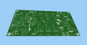
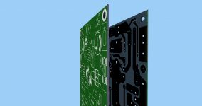
Terry ? I'm, confuse 😕, I thought mirror is when you are using UV light photosensitive PCB copper clad ? see images 🙂
Attachments

Last edited:
Terry ? I'm, confuse 😕, I thought mirror is when you are using UV light photosensitive PCB copper clad ? see images 🙂
When you use iron transfer, the image is reversed. When you use photo sense it is not. The biggest hint is when there are words in the image. For iron transfer they will no be legible.
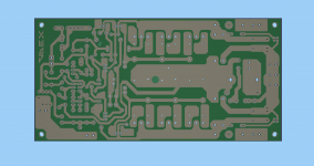
Here are iron transfer for the 3P boards.
Attachments
Last edited:
I try it and this software have a virtual ruler, the number is not accurate but close enough, sadly I do not have more ink on my printer 🙁 to print this in grey scale to safe ink 🙂
Hi Vargas,
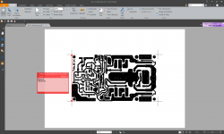
The best way I found is to print individual layers using foxit pdf printer and then import files in coreldraw to do mirrors, positives, negatives, etc. One can also confirm the dimensions in coreldraw (its accurate!). Then exporting from corel to pdf results in very accurate pdfs that are exactly same as the cad software.
reg
Prasi
Here are iron transfer for the 3P boards.
Hi Terry, only Silkscreen needs to be mirror and copper is printed without mirror for iron transfer.
Juan you are having weird problem, I was able to print pdf accurately.
Attachments
Last edited:
Hi Terry, only Silkscreen needs to be mirror and copper is printed without mirror for iron transfer.
Juan you are having weird problem, I was able to print pdf accurately.
Sorry I wasn't paying attention. Here is the correct iron transfer copper file
Attachments
FX8 Bimo Mod in Stereo
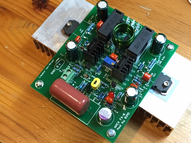
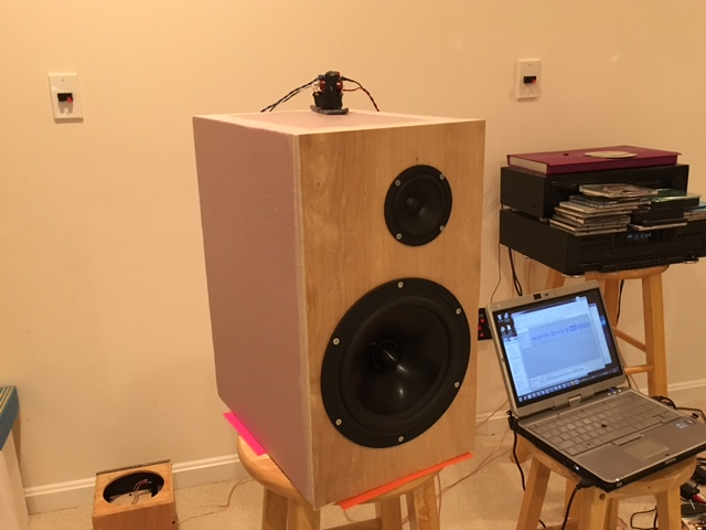
I finally got some time to build the second channel of the FX8 Bimo Mod. Listening to it in stereo on my 10F/8424 RS225-8 transient perfect FAST speakers. Sounds wonderful - Dave Brubeck's Take 5 in HD FLAC. This is a nice sounding amp 🙂
Closeup before power on:
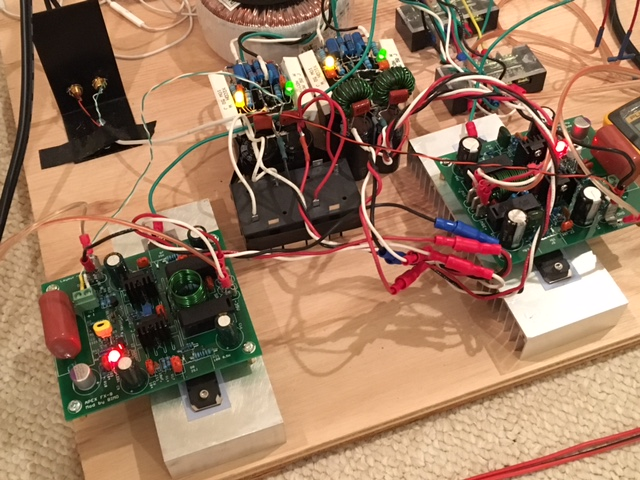
Running in stereo with 35v PSU and bias current set at 175mA:
TP FAST Speaker:
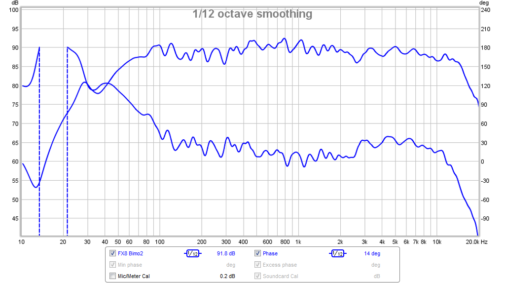
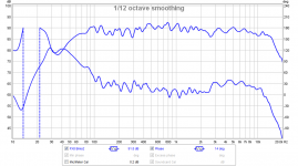
Here is the measured frequency response and phase of the speaker as driven by this amp:
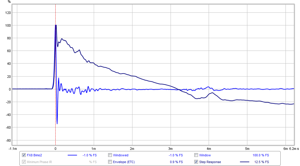
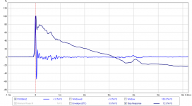
Here is the measured impulse and step response:
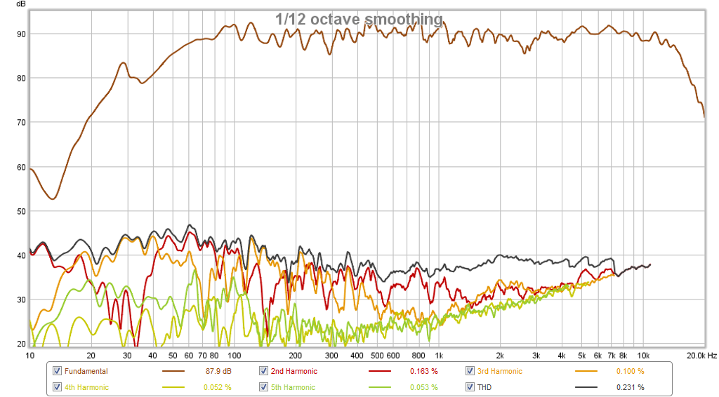
Here is the measured harmonic distortion:
I finally got some time to build the second channel of the FX8 Bimo Mod. Listening to it in stereo on my 10F/8424 RS225-8 transient perfect FAST speakers. Sounds wonderful - Dave Brubeck's Take 5 in HD FLAC. This is a nice sounding amp 🙂
Closeup before power on:
Running in stereo with 35v PSU and bias current set at 175mA:
TP FAST Speaker:
Here is the measured frequency response and phase of the speaker as driven by this amp:
Here is the measured impulse and step response:
Here is the measured harmonic distortion:
Attachments


Last edited:
Hi X,
Nicely done. I see that you have all the proper parts and everything fits perfectly. Have you used all ceramic caps as per Bimo's recommendation? BTW nice inductor winding. how is the bass?
reg
prasi
Nicely done. I see that you have all the proper parts and everything fits perfectly. Have you used all ceramic caps as per Bimo's recommendation? BTW nice inductor winding. how is the bass?
reg
prasi
Last edited:
Hi Prasi,
Wonderful job you did on the layout! Yes, everything fits perfectly. The only part I am missing and had to kluge was the 0.5w 22k resistor, so I paralleled two 47k 1/4w resistors. I am using disc ceramic caps for all values below 100nF and film caps above. Input cap is a 10uF 250V MKT Panasonic bypassed with CBB 100nF 100V MKT. 1uF caps are CBB 63v MKT. Power rail caps are Nichicon 470uF 50V and feedback cap is 330uF 25v Panasonic OSCON. The inductor is 18ga enameled wire wrapped around a AA battery. I like the vertical orientation better - that way I don't have to put the resistor inside so it truly is an "aircoil". The speaker certainly doesn't show any distortion induced by the amp. Very clean sounding. Speakers are running -45 to -50dB distortion which is basically the native limit of the ScanSpeak 10F.
Wonderful job you did on the layout! Yes, everything fits perfectly. The only part I am missing and had to kluge was the 0.5w 22k resistor, so I paralleled two 47k 1/4w resistors. I am using disc ceramic caps for all values below 100nF and film caps above. Input cap is a 10uF 250V MKT Panasonic bypassed with CBB 100nF 100V MKT. 1uF caps are CBB 63v MKT. Power rail caps are Nichicon 470uF 50V and feedback cap is 330uF 25v Panasonic OSCON. The inductor is 18ga enameled wire wrapped around a AA battery. I like the vertical orientation better - that way I don't have to put the resistor inside so it truly is an "aircoil". The speaker certainly doesn't show any distortion induced by the amp. Very clean sounding. Speakers are running -45 to -50dB distortion which is basically the native limit of the ScanSpeak 10F.
Last edited:
Hi Prasi,
Wonderful job you did on the layout! Yes, everything fits perfectly. .... .
great work X, congrats 🙂
great work X, congrats 🙂
Thanks. I have been listening to it all day. It's a nice sounding amp and surprisingly easy to build. More people should try the FX8 Bimo mod. It's got some special upgraded transistors up stream of the lateral FETs that make it sound really good.
Thanks. I have been listening to it all day. It's a nice sounding amp and surprisingly easy to build. More people should try the FX8 Bimo mod. It's got some special upgraded transistors up stream of the lateral FETs that make it sound really good.
A friend who built this amplifier made latfet bias around 400mA, of course with big heatsink. He said it sound better than my suggested bias (150mA).
I'll try that 400mA bias. I can add a noiseless fan and it can handle class A loads even. Noiseless fan is simply regular 12vdv brushless fan with 100R 2w resistor in series with supply.
A friend who built this amplifier made latfet bias around 400mA, of course with big heatsink. He said it sound better than my suggested bias (150mA).
SUBJECTIVELY better. I always bias latfet at 110mA. If you want better sound, get more latfets!
BTW, the bias current is part of given variables (operating conditions) that you set before you decide on the rest of the schematic. So it is not like (simply) changing a bias pot to adjust to your preferred bias current. Otherwise it will change the operation of the rest of the circuit, at least the driver.
Last edited:
I tried the 400mA bias and doesn't sound any better to my ears. The speakers already measured extremely low distortion at 175mA. Maybe I will try Jay's 110mA and run even cooler to see orbit still sounds good. Sure gets hot at 400mA though.
SUBJECTIVELY better.
May be.
BTW, the bias current is part of given variables (operating conditions) that you set before you decide on the rest of the schematic. So it is not like (simply) changing a bias pot to adjust to your preferred bias current. Otherwise it will change the operation of the rest of the circuit, at least the driver.
Not at bias current of output transistors, I think. Especially wit latfet that high impedance input.
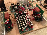
I am running 110mA now and seems to still sound good and heat is less than previous 400mA or 175mA. I am making a new boxed amp for my Vhex so needed to take away the dual PSU's. In it's place I have returned the Dx PSU (now fitted with fuses) and also a big LC cap bank with about 25,000uF (4700uF + 20 x 1000uF) of caps per rail. There design called for two separate 2.2mH toroid chokes (special material high saturation cores) on each DC rail. I happened to have a Coilcraft 2.5mH CMC with a split core. I added 0.22R 5W in series to match the DCR of the specified choke. I am not sure if the CMC used here will work or not. The whole system now has 15mV ripple vs 50mV without the cap bank. Here it is powering the two FX8 Bimo Mod boards.

Attachments
Hello everybody! if you're interested, you can watch my video -SMPS with Apex AX-14. https://www.youtube.com/watch?v=jL8MYMJ5lqY less than half of the volume, the house is very loud. My speakers can not play so powerfully
Interesting,can you share the smps files?Hello everybody! if you're interested, you can watch my video -SMPS with Apex AX-14. https://www.youtube.com/watch?v=jL8MYMJ5lqY less than half of the volume, the house is very loud. My speakers can not play so powerfully
- Home
- Amplifiers
- Solid State
- 100W Ultimate Fidelity Amplifier