And are they needed?
Hi Sjoerd!
The heatsinks originate from a larger heatsink from which I cutted two pieces by using a Dremel multitool. In addition I tapped M3 fittings with a tapping tool. You can obtain nice heatsinks from for example old processor coolers (especially those Pentium I / 486 coolers). To be honest those heatsinks are not really necessary, but hey oversizing things is fun eh ;-).
Updated January 15 2016
I've put the complete write-ups for the nx-Amplifier and sx-Amplifier up on my website hifisonix.com
If you want to make 'em, including where to buy PCB's, everything is there - look under the respective amplifier posts.
nx-Amplifier
100W RMS into 8 Ohms CFA class AB Amplifier featuring DC-570 kHz bandwidth, <1us rise times, ~200 V/us slew rate. Uses +-45 to +-50V Power Supply. PSU +Protection board with Mosfet SSR provides overcurrent, DC offset and on/off muting.
The new V2.0 nx-Amplifier PCB incorporates all of the errata changes and suggestions made by builders over the last year: Ovation nx-Amplifier: A 100 W class AB Current Feedback Amplifier
Download the nx-Amp V2.09 build document here The Ovation nx-Amplifier V2.0_9 | hifisonix.com
You can also buy a set of very high quality double sided through hole plated, silk screened gold flashed V2.0 boards from Jim's Audio here: 100Wx2 Ovation nx Current Feedback Amplifier PCB set new version 2.0 ! | eBay
sx-Amplifier
15W RMS into 8 Ohms current feedback class A amplifier, 28 Watts peak class A into 8 Ohms. DC-530 kHz (-3 dB) bandwidth, 140 V/us slew rate and rise times <1 us. Uses +-20V to +- 22V DC power supply . You can download the full amplifier write-up and build document here: http://hifisonix.com/the-sx-amplifier-v2-10/ (updated March 2016)
You can buy a set of very high quality double sided, through hole plated gold flashed sx-Amplifier PCB's from Jim's Audio here: 15Wx2 class A 25Wx2 class AB Ovation sx-Amplifier Current Feedback PCB set ! | eBay
Notes About Components
The BC547 and BC557 have been discontinued by a number of suppliers and this has lead to problems in both the sx-Amp and the nx-Amp for some builders.
In place of the BC547(C) NPN devices you can use the BC550(C) - data sheet here https://www.fairchildsemi.com/datasheets/BC/BC547.pdf
For the originally specified BC557(c) PNP devices you can use the BC560(c) - data sheet here https://www.fairchildsemi.com/datasheets/BC/BC557.pdf
You can use either the C suffix with an hFE range of ~400 to 800 or the B suffix with an hFE range of ~200 to 450. I suggest if you can use the C suffix, then that should be the first option. However, note that you should use the same hFE suffix for both the NPN and the PNP small signal transistors.
😎🙂
THx-Richard
Hi Kaplaars,
Traded in my 486 a while ago🙂
You are right! It's best when totally overdone🙂
Ps: I think you got the last two Mundorf caps in Europe!
Traded in my 486 a while ago🙂
You are right! It's best when totally overdone🙂
Ps: I think you got the last two Mundorf caps in Europe!
Last edited:
Using my SX every day. Great amp!
🙂
Very happy that you are enjoying your sx-amp!
add in a DC blocking capacitor at the input.
Then set the output offset with the DC blocker in place.
It makes a big difference to the variation in output offset.
Mine wandered all over the place while I was still in the testing phase on the bench.
I used a 10uF film dielectric.
The offset still moves around more than any of my previous LTP style inputs, but manageable. Very temperature dependent.
Hi Andrew, I don't have that problem. Tested the boards and all is steady. I managed 0,2 to 2mvDC
But the NX will be powered on my DIY power conditioner and it is fitted with a DC blocker, just in case.
Sjoerd
But the NX will be powered on my DIY power conditioner and it is fitted with a DC blocker, just in case.
Sjoerd
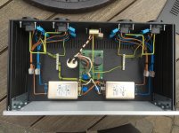
Nice work Sjoerd! But be carefull with those RIFA's (if they are RIFA's, am not sure). They tend to explode/burn/cause ALOT of smoke after a few years because the dielectric is highly hygroscopic and probably not properly sealed anymore after many years. Those caps caused already caused quite a few times Syrian conditions over here in the lab ;-) Yes, even the X2, Y1 types ;-).
An externally hosted image should be here but it was not working when we last tested it.
.jpg)
Thanks for the tip! These are brand new x1 and y1 types. Yes, Rifa. I will replace them in a few years 🙂
add in a DC blocking capacitor at the input.
Then set the output offset with the DC blocker in place.
It makes a big difference to the variation in output offset.
Mine wandered all over the place while I was still in the testing phase on the bench.
I used a 10uF film dielectric.
The offset still moves around more than any of my previous LTP style inputs, but manageable. Very temperature dependent.
Andrew, the DC stability of these simple CFA amps is very good once the initial offset is dialed out - but you must do this AFTER the amp has fully warmed up. Note that from cold switch-on to fully warmed up a class A sx-Amp will take about 30 minutes. Only after its warmed up can you properly adjust the output offset to zero. On subsequent cold switch-on's, about 80% of the offset will disappear in the first 4-5 minutes and the rest over the next 25 mins.
The offset from subsequent cold switch-on's is then about 50mV, after 4-5 minutes about 10mV and after 30 minutes it should be low single digit - 2-3mV is about right.
If you suspect your source has any DC offset, you should use a DC blocking capacitor. 10uF is a good value and will ensure that the response at 20 Hz is not down by more than -0.1 dB
Sure, glad I could help 🙂. I have had very good results with those blue plastic ones (those you also have). These are really reliable, especially the BC ones. I think it has to do something with the sealing compound on those yellow trigger happy caps that somehow turns from the glass state to a mere liquid state after years. This makes them permeable to water and leading to problems.
Very curious about the DC-offset. Worst case scenario; it is then maybe not convenient to add a DC servo Andrew? Or could you improve it a bit by getting the sense transistor closer to the heatsink (that little BC847 if I recall correctly)?
I have currently all parts soldered except the output transistors. But I first need to find a cabinet for that (and some $$$ hehe). Here some pics:
An externally hosted image should be here but it was not working when we last tested it.
An externally hosted image should be here but it was not working when we last tested it.
Looks good Kaplaars! I hate the fact that you got those really nice caps on your psu ;-) Mine are in backorder.
Case is REALLY expensive. I was lucky to get hold of one that was leftover at Modu. So I payd a bit less. Still a steap amount though...
Sjoerd
Case is REALLY expensive. I was lucky to get hold of one that was leftover at Modu. So I payd a bit less. Still a steap amount though...
Sjoerd
DC servo's are very good - but both the sx and nx amplifiers are minimalist designs. Once you have set them up correctly they are fine and will perform without issue.
Note that on the nx-Amp, the offset settling time is much quicker
Nice looking boards by the way!
🙂
Note that on the nx-Amp, the offset settling time is much quicker
Nice looking boards by the way!
🙂
it is not anything to do with DC from the source.Andrew, the DC stability of these simple CFA amps is very good once the initial offset is dialed out - but you must do this AFTER the amp has fully warmed up. Note that from cold switch-on to fully warmed up a class A sx-Amp will take about 30 minutes. Only after its warmed up can you properly adjust the output offset to zero. On subsequent cold switch-on's, about 80% of the offset will disappear in the first 4-5 minutes and the rest over the next 25 mins.
The offset from subsequent cold switch-on's is then about 50mV, after 4-5 minutes about 10mV and after 30 minutes it should be low single digit - 2-3mV is about right.
If you suspect your source has any DC offset, you should use a DC blocking capacitor. 10uF is a good value and will ensure that the response at 20 Hz is not down by more than -0.1 dB
It's the instability of the single ended input stage with respect to temperature.
This is compounded by sensitivity to the source impedance seen by the DC coupled connection.
The pair give rise to an output offset that wanders all over the place compared to an LTP style input stage that is AC coupled.
I had never built a DC coupled amplifier with a single ended input. The NX proved to me how bad that combination is.
Last edited:
it is not anything to do with DC from the source.
It's the instability of the single ended input stage with respect to temperature.
This is compounded by sensitivity to the source impedance seen by the DC coupled connection.
The pair give rise to an output offset that wanders all over the place compared to an LTP style input stage that is AC coupled.
I had never built a DC coupled amplifier with a single ended input. The NX proved to me how bad that combination is.
That is a shame. But, problems are there to be solved; how could this problem be tackled according to your expertise? You suggest that it is a problem intrinsic to the design. However, from what I read in this topic you seem to be the only builder that has this problem. Could there not be a different explanation?
I currently have not the facilities to check how my NX behaves, but I am curious to what causes this. Have you tried to improve it by for example putting the sense transistor closer to the heatsinks? Is everything matched etc.?
- Home
- Amplifiers
- Solid State
- SX-Amp and NX-Amp