Hi,
This is the way I send a message out to the display.
zbasic command;
msg_str = "hello cruel World!!!!!!"
call PutQueuestr(ocom3,chr(254) & chr(69) & msg_str )
PutQueuestr() = output instruction command
ocom3 = define port output = pin out
chr(xx) are control characters.
msg_str = buffer string
This is the way I send a message out to the display.
zbasic command;
msg_str = "hello cruel World!!!!!!"
call PutQueuestr(ocom3,chr(254) & chr(69) & msg_str )
PutQueuestr() = output instruction command
ocom3 = define port output = pin out
chr(xx) are control characters.
msg_str = buffer string
You guys need more "grunt" to do all this fancy stuff with I2C.
https://www.arduino.cc/en/ArduinoCertified/IntelGalileo
Sort of like an Intel atom with the arduino ecosystem.
OS
https://www.arduino.cc/en/ArduinoCertified/IntelGalileo
Sort of like an Intel atom with the arduino ecosystem.
OS
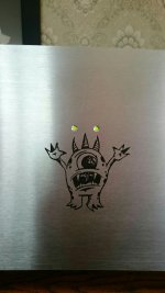
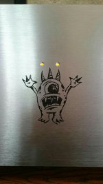
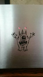
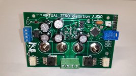
Finally got around to change the code and install my RG leds today. 🙂
Now I have red for standby, orange for inrush and green for ready. 🙂
I also made alarms with various combinations so that I can see clearly what fault it tripped from.
Now I have red for standby, orange for inrush and green for ready. 🙂
I also made alarms with various combinations so that I can see clearly what fault it tripped from.
Attachments
Not so sure even with magnifying lenses I would want to solder that one control chip, that looks crazy. What would it cost to have just the really small smd devices installed professionally? I could see how easy it would be to mess that up and have solder bridges.
I've never priced having boards preassembled for me. I don't trust them to use genuine parts. It's actually quite easy to solder these with a little practice, a good iron and some .015" solder. Solder wick and a good solder sucker will fix any bridge. I have a Luxo Lamp with a magnifying glass on my bench, but rarely use it.
So how do the reflow systems work and is that appropriate for diy? My eyes ain't that great anymore, getting old enough to think better of that!
Reflow works great if you get a stencil made up for your solder paste. You need good temperature control, or the silk screen scorches though.
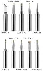
can't see the vid here at work but if it's about drag soldering 0.65mm pitch chips I do that and it is surprisingly easy. Just dab solder two pins at the corners to secure the chip in place, then bluntly solder all the pins without worrying about the short circuiting. Then solder-wick away the excess and voila! Always use PLENTY of flux. Wide iron tips, such as the type-K tip in the picture, helps cover as many as possible pins.
Attachments
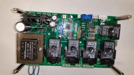
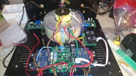
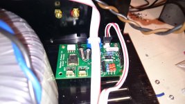
Another protection system almost finished. This is my Honey Badger using the amp control 4.32 boards.
It took me a while (and a Uln2003a) before I figured out that the header on the relay board had to be mounted on the bottom in order to use ribbon cable.
So far I have tested softstart, DC alarm and temperature. It trips immediatly when I have the soldering iron set to 125 degrees and touch the mje340. 🙂
These boards are just as much fun as building the actual amplifier.
Soon time to hook up the amp and finish all the wiring. 🙂
Attachments
Another protection system almost finished. This is my Honey Badger using the amp control 4.32 boards.
It took me a while (and a Uln2003a) before I figured out that the header on the relay board had to be mounted on the bottom in order to use ribbon cable.
So far I have tested softstart, DC alarm and temperature. It trips immediatly when I have the soldering iron set to 125 degrees and touch the mje340. 🙂
These boards are just as much fun as building the actual amplifier.
Soon time to hook up the amp and finish all the wiring. 🙂
Very nice build. I actually like your approach - also trying to follow this order of priorities - control and protection go first. Later on, some things may go wrong (during initial testing - normal thing 😛), but it's good to know that the board will do as much as possible to save the amp and the speakers 😎
Very nice build. I actually like your approach - also trying to follow this order of priorities - control and protection go first. Later on, some things may go wrong (during initial testing - normal thing 😛), but it's good to know that the board will do as much as possible to save the amp and the speakers 😎
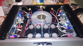
Thanks. I'm not completely happy with the layout, would probably do it different if I built it from scratch, but this is the first amplifier I ever built. It have been in service for one year without any protection before I tore it apart to install the amp control boards, so the control board it self had to go in the location where the softstart board used to be below the filter caps. The rest of the boards had to go wherever there was space left.
It's gonna be tight when everything is installed, here's how it looked before I started.
Anyways, good to know that all protection circuits are working before putting it in service. 🙂
Attachments
A question regarding the thermal detection with the MJE340's - how have people mounted them with respect to placement on the heatsink?
In my case with 3 output pairs per channel, is there a common school of thought as to where is an effective monitoring position?
I've got a piece of aluminium flat spreader common to my transistors, is this a reasonable mounting site?
The question in the back of my mind is what if one device is running hot, but it's not enough to raise the total temp to the overheat threshold....
I guess the answer would be that this is a device failure issue which the current sensing would catch? Which, if I'm on the right track would suggest that the over current protection trigger should be for the whole string of output devices rather than a single pair?
Does this sound right or have I wandered off target? 🙂
- Home
- Amplifiers
- Solid State
- How to build a 21st century protection board