Member
Joined 2009
Paid Member
When I first looked at this hybrid approach it was my first ever post in the tubes forum, I knew nothing !
http://www.diyaudio.com/forums/tube...g-triode-fet-complementary-feedback-pair.html
http://www.diyaudio.com/forums/tube...g-triode-fet-complementary-feedback-pair.html
preliminary thd plots
The file name describes plot. To make all happy, I'm plotting to 25khz at 192.
I'm gradually increasing output power in increments as a detailed study.
Final target power is 10watts. These plots are headphone level.
Again: same two active component CFP , 12au7 and a single semiconductor.
cheers.
The file name describes plot. To make all happy, I'm plotting to 25khz at 192.
I'm gradually increasing output power in increments as a detailed study.
Final target power is 10watts. These plots are headphone level.
Again: same two active component CFP , 12au7 and a single semiconductor.
cheers.
Attachments

The file name describes plot. To make all happy, I'm plotting to 25khz at 192.
Hint: slew rate... ;-)
Hint: slew rate... ;-)
don't know it looks great at 100khz , no compensation cap needed either.
Time to connect VU-meters... Enough listening... ;-)
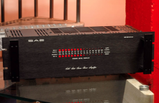
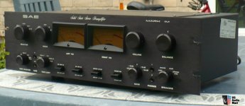
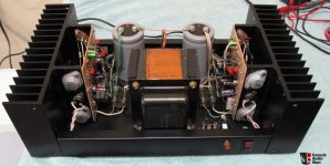
I was out looking for donor chassis yesterday and picked up a SAE 2200 power amp for $60 with led 'VU' meters.
I thought it was going to look silly but was really nice to watch.
So will leave it alone and get another donor.
also the circuit now has enough power to properly drive a reverb pan and tone stack.
going to need a serious heat sink for next stage.
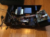
hafler has some old mega heat sink models that can be found either on ebay 'for parts only'
or just plain cheap.
this pic is dh200.
p3000 has biG find too.
-
or just plain cheap.
this pic is dh200.
p3000 has biG find too.
-
Attachments
Last edited:
so on vacation now, away from the lab.
now have time for exploring some theory.
i remember the first time i heard an open loop class-a amplifier.(it used a old delco Germanium doorknob pnp with resistor loading)
not using common accepted design practices wasn't really expecting much.
it turnd out to be an epifiny moment.
was it magic or a trick of the mind? a placebo?
now digging more into the bench test using
https://www.google.com/patents/US54...ved=0ahUKEwidx-zumpjNAhUIWCYKHT71BrEQ6AEIHDAA
No miller effect? And now combining low distortion without global feedback maybe going down the right path.
Why listener 'fatigue' on common AB solid state with long tail?
I keep going back to the epifiny 'love at first sight' moment.
Maybe the answer is much more complex.
And then why have some classic AB sound great?
Looking at the units that did , they all had capacitor coupled outputs. ie marantz 1060. Its very confusing, maybe chemical response?
Attachments
Subscribed
Jfetter, very interesting. Thanks for sharing your thoughts. I am a bit surprised the circuit shown would be patentable as it appeared (substantially) in 1966:
http://www.spontaflex.free-online.co.uk/pentonlector/circuit.jpg
I have built some variations of this amp using both si and ge outputs, Stancor TA-50 autoformer, and 15CW5 tube at about 20 volt supply. Some results were very pleasing but not measured. An efficient speaker is required. Simple and sweet.
Terry
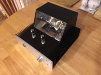
This one will look like tank. 🙂
nice.
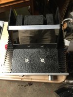
I was re-arranging my test equipment and had all the enclosures turn around so heat sinks were facing out. Wow I think its an accidental discovery. I like the Klingon equipment look.
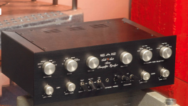
hybrid pre update
This is tested and looks promising as a keeper.
-bias ckt can be simplified but want to keep where I can plug in fets.
-still working on correct gain equation using R5/R10, almost done
-of course other voltages could be used, I have tested +-35v
cheers
This is tested and looks promising as a keeper.
-bias ckt can be simplified but want to keep where I can plug in fets.
-still working on correct gain equation using R5/R10, almost done
-of course other voltages could be used, I have tested +-35v
cheers
Attachments
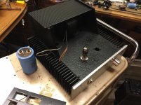
Transformers are bolted... Going to solder.
looking at your chrome i realized an easy way to get 'chrome panels' using Mcintosh's sandwich concept.
Just put the 'chrome' behind a lexan or glass sheet. For chrome maybe use Monokote foil.
-
Attachments
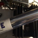
looking at your chrome i realized an easy way to get 'chrome panels' using Mcintosh's sandwich concept.
Just put the 'chrome' behind a lexan or glass sheet. For chrome maybe use Monokote foil.
-
I am afraid Lexan is not transparent for IR?
I use stainless steel. It is reflective, and have low thermal conductivity.
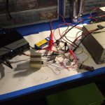
Grid leak test
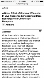
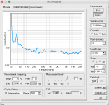
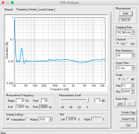
Here is a grid leak test arising from pre-amp thread, only change is series 1M resistor for the test itself. Same +-25VDC supply.
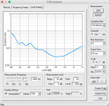
As on the SS version, THD actually does down due to the introduced input divider.
Some new HF loss is seen and low f distortion artifacts. The test resistor is normally not present.
The big pot is R2 and trim pot is bias.
Note: the response plot(s) includes pink noise version
The UR22 has 150 ohm output z feeding the 1M resistor, UR22 input z is normal channel 20k ohm z.
The tube is a new JJ with about 4 hours on it, using Heathkit IP-17 HV lab power supply 12vac heater.(not shown)
File names have description of pic.
Cheers
Bruce
-
Here is a grid leak test arising from pre-amp thread, only change is series 1M resistor for the test itself. Same +-25VDC supply.
As on the SS version, THD actually does down due to the introduced input divider.
Some new HF loss is seen and low f distortion artifacts. The test resistor is normally not present.
The big pot is R2 and trim pot is bias.
Note: the response plot(s) includes pink noise version
The UR22 has 150 ohm output z feeding the 1M resistor, UR22 input z is normal channel 20k ohm z.
The tube is a new JJ with about 4 hours on it, using Heathkit IP-17 HV lab power supply 12vac heater.(not shown)
File names have description of pic.
Cheers
Bruce
-
Attachments
-
Hybrid-SZpre-V0.6-Grid-leak-test.pdf17 KB · Views: 128
-
 grid-leak-1M-test.jpg365.3 KB · Views: 128
 -
 grid-leak-test-setup.jpg437.9 KB · Views: 128
 -
 Input-Level-vs-thd-2khz.png34.5 KB · Views: 107
 -
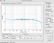 Response-Pink-1M-series-0db.png34.1 KB · Views: 114
 -
 THD-1M-series-6db-input.png36.1 KB · Views: 115
 -
 THD-1M-series-0db-input.png34.6 KB · Views: 350
 -
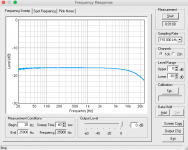 Response-1M-series-0db.png32.6 KB · Views: 125
Last edited:
- Status
- Not open for further replies.
- Home
- Live Sound
- Instruments and Amps
- hybrid output