I've been an audio engineer for well over a decade now, and I trust my ears much more than SMAART or PCD or REW or whatever. I've even designed well-liked and used FIR filters for a very popular live PA speaker.
That being said, when it comes to electronics, I'm an idiot. I've designed a few pairs of speakers that sound pretty good; but, I feel like I'm skating by on luck with my designs in PCD. I don't REALLY know how to tweak a crossover.
I get it, buy a slightly smaller value component than predicted and add tiny values to it to suit your ears. Ok, but physically how do I wire that? For inductors is that in series (Add a .1 to a .5 in series to get .6)? Capacitors stacked on top of eachother? Resistors? I can't seem to make sense of it!
I would gladly accept a link so somewhere else to read about this. I just can't figure out how to apply electronics 101 to crossover tweaking. Maybe I have a great pair of ears with a dull brain in between them. . . Any help appreciated here.
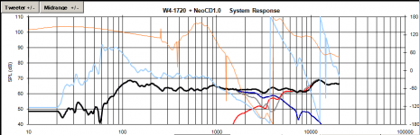
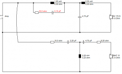
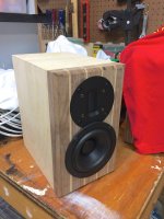
FYI - Attached is the design I'm working on - recently found out it's actually a popular driver config by Carmody - but I had no idea when I started, and my XO looks way different. It's a gift for my wife who is graduating medical residency and I just want it to be right. It will be paired with a Model 1060 Marantz and a record player of some sort.
That being said, when it comes to electronics, I'm an idiot. I've designed a few pairs of speakers that sound pretty good; but, I feel like I'm skating by on luck with my designs in PCD. I don't REALLY know how to tweak a crossover.
I get it, buy a slightly smaller value component than predicted and add tiny values to it to suit your ears. Ok, but physically how do I wire that? For inductors is that in series (Add a .1 to a .5 in series to get .6)? Capacitors stacked on top of eachother? Resistors? I can't seem to make sense of it!
I would gladly accept a link so somewhere else to read about this. I just can't figure out how to apply electronics 101 to crossover tweaking. Maybe I have a great pair of ears with a dull brain in between them. . . Any help appreciated here.
FYI - Attached is the design I'm working on - recently found out it's actually a popular driver config by Carmody - but I had no idea when I started, and my XO looks way different. It's a gift for my wife who is graduating medical residency and I just want it to be right. It will be paired with a Model 1060 Marantz and a record player of some sort.
Attachments
Hi,
Caps in series decrease value
Caps in parallel increase value
Res in series increase value
Res in parallel decrease value
Ind in series increase value
Ind in parallel decrease value
Have a look/try here for eg Capacitors - Parallel and Serial Connections
Caps in series decrease value
Caps in parallel increase value
Res in series increase value
Res in parallel decrease value
Ind in series increase value
Ind in parallel decrease value
Have a look/try here for eg Capacitors - Parallel and Serial Connections
Try my blog posting here.
A Speaker Maker's Journey: Crossover Basics
There you will find a link to Xsim which will make a very good learning lab.
Best,
Erik
A Speaker Maker's Journey: Crossover Basics
There you will find a link to Xsim which will make a very good learning lab.
Best,
Erik
A useful thing to do is to "bake in" some adjustment into your crossover design.
i.e. Try adding resistors in series with all the caps/inductors and changing existing resistors to see the effects. Work out if you can adjust a large range of frequencies up/down a couple dB without messing up the phase alignment by changing just by changing the resistances. Then if you find a certain range of frequencies is sounding too hot or recessed after you build it, it's easy to fix. You could even take it further by adding a switch to the cabinet so you can select different resistors.
i.e. Try adding resistors in series with all the caps/inductors and changing existing resistors to see the effects. Work out if you can adjust a large range of frequencies up/down a couple dB without messing up the phase alignment by changing just by changing the resistances. Then if you find a certain range of frequencies is sounding too hot or recessed after you build it, it's easy to fix. You could even take it further by adding a switch to the cabinet so you can select different resistors.
Last edited:
Attached is the design I'm working on - recently found out it's actually a popular driver config by Carmody.
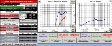
From looking at that crossover (system response chart), I suggest that you build the design by Paul Carmody.
From looking at that crossover (system response chart), I suggest that you build the design by Paul Carmody.
Just for kicks and giggles I typed in his component values and got a pretty crazy response. My driver response data seems to be very different than his, and I trust my data as it was taken in box and at several angles to verify all anomalies. I agree that ultimately his SPL graph looks better, but just typing in his values doesn't seem to do it for me.
Just for kicks and giggles I typed in his component values and got a pretty crazy response.
Can you show that response? The frequency response itself is not too important in such simulation. You can make 10 very different networks and the responses are more or less the same, right? (but the sound quality will not be the same).
BTW, I think the data was not right.
Hi,
Caps in series decrease value
Caps in parallel increase value
Res in series increase value
Res in parallel decrease value
Ind in series increase value
Ind in parallel decrease value
Have a look/try here for eg Capacitors - Parallel and Serial Connections
Zero D - Thank you. I don't know why I couldn't find it stated so simply somewhere else! Just to make sure I understand the practical application, when wiring a component in series I literally just add it in line after another, but parallel I just stack them with their leads touching on both sides, right? Not sure why it so easy for me to understand with speakers but not XOs 🙂
Correct.Just to make sure I understand the practical application, when wiring a component in series I literally just add it in line after another, but parallel I just stack them with their leads touching on both sides, right?
When you wire inductors or resistors in series, the values simply sum together. Same thing with wiring capacitors in parallel.
Wiring multiple components to reduce the overall value gets trickier - this when you would wire two inductors or resistors in parallel, or two capacitors in series. The resulting value is C = 1/((1/A)+(1/B)) where A and B are the values of the two components and C is the resulting value when you wire then together. As a result of this if you only want to reduce the value of a component by a little bit then you need another component which is much much larger in value. For instance, if you wire a 8ohm resistor in parallel with 100ohms you get 1/((1/8)+(1/100)) = 1/(0.135) = 7.41ohms. Obviously if you had an 8uF capacitor or 8mH inductor and you wanted to reduce it's value to 7.4 it would be hopelessly impractical to go and get an 800uF or 800mH component hence why the rule of thumb is to start with a components which are lower than nominal then increase them as neccesary by adding smaller components. The exception to this are inductors since you can buy one that is too large and them simply unwind some turns until you reach the required value - assuming of course you have the equipment to measure inductance.
One other thing to note when using multiple inductors is that you still need to observe physical placement rules even if they are wired together!
Placement of coils in crossover networks
Last edited:
Correct.
When you wire inductors or resistors in series, the values simply sum together. Same thing with wiring capacitors in parallel.
Wiring multiple components to reduce the overall value gets trickier - this when you would wire two inductors or resistors in parallel, or two capacitors in series. The resulting value is C = 1/((1/A)+(1/B)) where A and B are the values of the two components and C is the resulting value when you wire then together. As a result of this if you only want to reduce the value of a component by a little bit then you need another component which is much much larger in value. For instance, if you wire a 8ohm resistor in parallel with 100ohms you get 1/((1/8)+(1/100)) = 1/(0.135) = 7.41ohms. Obviously if you had an 8uF capacitor or 8mH inductor and you wanted to reduce it's value to 7.4 it would be hopelessly impractical to go and get an 800uF or 800mH component hence why the rule of thumb is to start with a components which are lower than nominal then increase them as neccesary by adding smaller components. The exception to this are inductors since you can buy one that is too large and them simply unwind some turns until you reach the required value - assuming of course you have the equipment to measure inductance.
One other thing to note when using multiple inductors is that you still need to observe physical placement rules even if they are wired together!
Placement of coils in crossover networks
TMM - my main man! Thank you for this. That's what I was thinking. I was just about to order the parts, I have small ones for tweaking in the cart but I think I'll drop the values a little for the main components so I can work up from there, instead of down.
If the choice is made to combine two inductors to create a new value (eg two in series to increase inductance, especially air cores or where two coils can be fitted to one appropriate core) it is reasonable to stack them to create the value using less copper. An inductance meter or method of measuring them is assumed.even if they are wired together!
I always like to look at what other talented people have done with a driver, here the Tang Band W4-1720:
Paul Carmody: https://sites.google.com/site/undefinition/speedster
Louis Coraggio: Piccolata Mini Monitor
It's a low inductance woofer and hence easy to filter, so they both employ the 3rd order trick on the bass of adding the inductance back, for steeper rolloff. Lou used a high notch on the woofer. Because it has some 10dB peak issues at 10kHz, which is only 20dB down with this filter.
I might try this 10kHz notch below on Paul Carmody's design, which is another way of doing things. It all looks quite good for a 4kHz crossover.
Attachments
Better, but still different.

Well, I hate to admit it, but Jay was right. Bad data (ish). I had the back wall removable for adding in the XO later and didn't have it sealed well at all leading to bad midrange info, as well as not having the tweeter screwed all the way flush. My prediction was fairly close to the measurement this time.
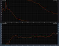
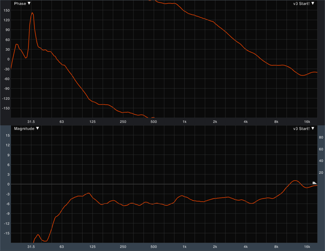
My XO is now more similar to what others have done. I have some pretty strong baffle diffraction leaving me with a bit of a gap in the presence region. I brought the top end of the woofer as much as I could without affecting the mids too much. If I bring the bottom of the HF up any more I lose my headroom, so I decided to leave it. These are a gift and very unfortunately I'm out of tweaking time after about only 2 hours. I may take a final listen before soldering.
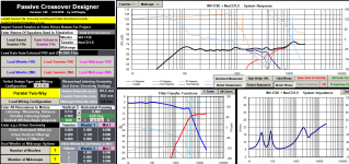
Here is my starting point after re-doing the measurements and XO. It looks like the whole 2kHz and surrounding octaves are a little hot, but when I dropped it down I really missed it. Played some Audioslave and the guitars cut without being harsh.
This will be paired with a Marantz Model 1060 and a record player, so the sizzle up top should come across fairly neutrally.
Well, I hate to admit it, but Jay was right. Bad data (ish). I had the back wall removable for adding in the XO later and didn't have it sealed well at all leading to bad midrange info, as well as not having the tweeter screwed all the way flush. My prediction was fairly close to the measurement this time.
My XO is now more similar to what others have done. I have some pretty strong baffle diffraction leaving me with a bit of a gap in the presence region. I brought the top end of the woofer as much as I could without affecting the mids too much. If I bring the bottom of the HF up any more I lose my headroom, so I decided to leave it. These are a gift and very unfortunately I'm out of tweaking time after about only 2 hours. I may take a final listen before soldering.
Here is my starting point after re-doing the measurements and XO. It looks like the whole 2kHz and surrounding octaves are a little hot, but when I dropped it down I really missed it. Played some Audioslave and the guitars cut without being harsh.
This will be paired with a Marantz Model 1060 and a record player, so the sizzle up top should come across fairly neutrally.
Attachments
Last edited:
Here is my starting point after re-doing the measurements and XO. It looks like the whole 2kHz and surrounding octaves are a little hot, but when I dropped it down I really missed it.
I'd listen to it for a week or so then go back to it being a bit hot and see if you still prefer it then 🙂
Tony.
I'd listen to it for a week or so then go back to it being a bit hot and see if you still prefer it then 🙂
Tony.
How I wish it were that easy! I left out that these are a surprise gift for my wife. I'm home most of the time these days, but can only take over an interior room for listening when she is on call overnight - and there is only one more of those until these are due (which will consist of soldering/installing XO, and applying oil to the finish)!
I think I should heed your advice, though. So maybe just a tiny bead of liquid nails (or whatever) instead of glue, so that if I change my mind I can get back in without too much fuss! Thoughts on that?
A reflex box really doesn't need to be that airtight, just solid to avoid rattles. Avoid glue at all costs. Screws are better, but seal the join with foam window seal or something.
AFAIK, you're building with Paul Carmody's Speedster drivers with a 6" baffle:
https://sites.google.com/site/undefinition/speedster
Paul is a bit weak on notches, IMO. But the FR is exemplary.
Your FR is a bit peaky at the top IMO:
Whatever are you doing to mess it up so badly? 😀
AFAIK, you're building with Paul Carmody's Speedster drivers with a 6" baffle:
https://sites.google.com/site/undefinition/speedster
Paul is a bit weak on notches, IMO. But the FR is exemplary.
Your FR is a bit peaky at the top IMO:
Whatever are you doing to mess it up so badly? 😀
Last edited:
A reflex box really doesn't need to be that airtight, just solid to avoid rattles. Avoid glue at all costs. Screws are better, but seal the join with foam window seal or something.
AFAIK, you're building with Paul Carmody's Speedster drivers with a 6" baffle:
https://sites.google.com/site/undefinition/speedster
Paul is a bit weak on notches, IMO. But the FR is exemplary.
Your FR is a bit peaky at the top IMO:
Whatever are you doing to mess it up so badly? 😀
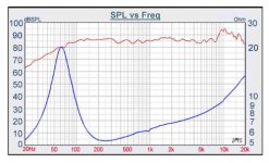
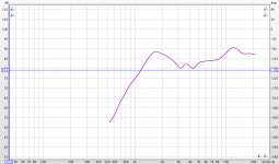
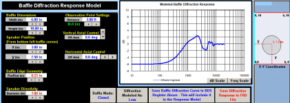
Seems you're right on most accounts. Posted is a pic of the tweeter raw SPL, in box, on axis, no EQ or XO. I verified the measurement with several different locations and programs. I also looked at it on JB's Response Modeler and it looks just like it said a 6" baffle would make it look. Also, his polarity is flipped and mine isn't. Not sure why mine looks so different up there. Wish it didn't.
Maybe I should check the other tweeter just to make sure it's consistent at least.
I disagree that it doesn't matter how airtight it is. My LF measurements were different by 5-6dB in places when I tightened everything down. And that hapenned to me before on a different pair of speakers, too.
Easy to see how I'm missing some presence from this pic!
Attachments
The crossover, drivers and layout and baffle width tell us most things about a speaker. 🙂
Can we see your crossover please with drivers, since it seems to be a straightforward 6" wide reflex flat baffle box?
Otherwise we are just guessing. It's all quite predictable really.
Can we see your crossover please with drivers, since it seems to be a straightforward 6" wide reflex flat baffle box?
Otherwise we are just guessing. It's all quite predictable really.
The crossover, drivers and layout and baffle width tell us most things about a speaker. 🙂
Can we see your crossover please with drivers, since it seems to be a straightforward 6" wide reflex flat baffle box?
Otherwise we are just guessing. It's all quite predictable really.
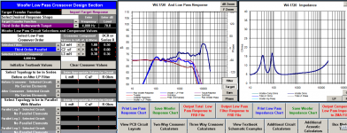
Ok, here is everything. Sorry the XO is just screenshots, I don't know how to put up those circuit layout images like everyone does.
The baffle diffraction image explains half of my HF measurement, but still not the peak up high. I might mount the other HF on a large baffle to see if it goes away.
Attachments
- Status
- Not open for further replies.
- Home
- Loudspeakers
- Multi-Way
- How to Tweak a Passive Crossover