Did anybody measure the values of the ladder resistors in the dam1021? I did today as I got curious and it looks like they are close to 10k and 5k on my board. Will make more measurements to see if they are 0.01/0,02%.
Last edited:
Did anybody measure the values of the ladder resistors in the dam1021? I did today as I got curious and it looks like they are close to 10k and 5k on my board. Will make more measurements to see if they are 0.01/0,02%.
You can't really measure resistors after they are installed in a circuit, the other parts of the circuit will throw off the measurements.
I trust that they meet what I ordered.
You can't really measure resistors after they are installed in a circuit, the other parts of the circuit will throw off the measurements.
I trust that they meet what I ordered.
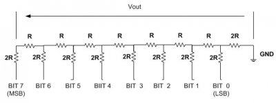
Well, if you look at the attached R2R circuit and assuming the resistance of shift register which any of these segments see is the same, would not R (or 2R) value measured individually be the same?
Attachments
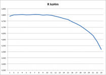
I measured the following R values (in one row):
Blue resistors (kohm)
4,789
4,800
4,801
4,802
4,800
Black resistors (kohm)
4,801
4,803
4,802
4,798
4,800
4,796
4,788
4,780
4,770
4,762
4,743
4,728
4,710
4,686
4,661
4,632
4,582
4,518
4.413
So, you was right. However, I am struggling to interpret the pattern for the first 10 R values.
Blue resistors (kohm)
4,789
4,800
4,801
4,802
4,800
Black resistors (kohm)
4,801
4,803
4,802
4,798
4,800
4,796
4,788
4,780
4,770
4,762
4,743
4,728
4,710
4,686
4,661
4,632
4,582
4,518
4.413
So, you was right. However, I am struggling to interpret the pattern for the first 10 R values.
Attachments
Last edited:
In case you really want to check:
1) Remove resistors from board VERY carefully as excessive heat ruins the resistors precision.
2) Ensure you do 4 wire measurements and have good contact.
3) Ensure you meter is accurate to 0.005% or better and have current calibration.
Have fun....
1) Remove resistors from board VERY carefully as excessive heat ruins the resistors precision.
2) Ensure you do 4 wire measurements and have good contact.
3) Ensure you meter is accurate to 0.005% or better and have current calibration.
Have fun....
One would have to be EXTREMELY motivated to do that!
I would be glad to remove them for someone but NO WAY IN HELL would I want to have to replace them!
After that nonsense: may I ask, are the vias for the OEM board the same size as on the original DIY boards?
Take care,
I would be glad to remove them for someone but NO WAY IN HELL would I want to have to replace them!
After that nonsense: may I ask, are the vias for the OEM board the same size as on the original DIY boards?
Take care,
Randy,
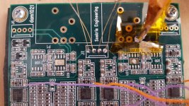
I just revisited your blog describing dam1021 mods. On the picture with opamps removed there are three black components left and above U28 (which is removed) with three legs. Do you know what are they for and if they could be removed.
I don't know that they are for.
I think I could remove them, but I haven't, so obviously am not sure.
If I remember correctly, Rick removed them.
Randy
After that nonsense: may I ask, are the vias for the OEM board the same size as on the original DIY boards?
Take care,
Yes, boards are using same PCB design rules.
I compiled some data on the voltage levels related to the resolution bits.
View attachment 471650
From that it looks like there are "only" 21-22 bits above the noise level of the DAM at 20 kHz bandwidth (which nearly is identical to the thermal (Johnson Nyqvist) noise that we have from the 650 Ohms of the DAC ladder at that bandwidth ... which is not avoidable).
So what are the benefits of 28 bits of resolution? That's not a rhetorical question, I do not rule out that the 28 bits are good for something, I currently only don't see for what.
I did not find any answers to this question. So, what is the true resolution of the dam1021?
I don't know that they are for.
I think I could remove them, but I haven't, so obviously am not sure.
If I remember correctly, Rick removed them.
Randy
Rick, would you know what are they for and if they could be removed?
In case you really want to check:
1) Remove resistors from board VERY carefully as excessive heat ruins the resistors precision.
2) Ensure you do 4 wire measurements and have good contact.
3) Ensure you meter is accurate to 0.005% or better and have current calibration.
Have fun....
Soren, thank you. I do not think I need to do that as I trust you and your products.
The reason I measured the value of resistors in the first instance was that during some modding I lost half of the left channel due to a short circuit somewhere and was looking for a failed component. I measure 8R2 on the output filter cap C135 and the same R value on the shift register's factory caps what is wrong as on the other shift register rails the impedance measured on the caps is in the range of kohms.
Perhaps you could give me a clue where the short circuit could be. Could potentially damaged shift register be the issue? ICs U28 and U29 are removed as well as opamps supplying 4V vref to the shift registers.
Last edited:
Soren, thank you. I do not think I need to do that as I trust you and your products.
The reason I measured the value of resistors in the first instance was that during some modding I lost half of the left channel due to a short circuit somewhere and was looking for a failed component. I measure 8R2 on the output filter cap C135 and the same R value on the shift register's factory caps what is wrong as on the other shift register rails the impedance measured on the caps is in the range of kohms.
Perhaps you could give me a clue where the short circuit could be. Could potentially damaged shift register be the issue? ICs U28 and U29 are removed as well as opamps supplying 4V vref to the shift registers.
Probably around the removed parts, unless you have applied too high voltage to the shift registers.... Shorts can be hard to locate, find your magnifier....
formatcd3,
I need to look and be sure but I feel almost certain I figured those were voltage regs for the opamps and removed them. It was a good while ago. About the only thing remaining on my board in the resistor stack area are the resistors and the shift registers. I cannot think of anything else that remains. BUT let me look this evening before proceeding. I will attempt a photograph.
PS I don't think it will ever be safe to return to the SDTrans thread! No more for me!!!
formatcd3,
I need to look and be sure but I feel almost certain I figured those were voltage regs for the opamps and removed them. It was a good while ago. About the only thing remaining on my board in the resistor stack area are the resistors and the shift registers. I cannot think of anything else that remains. BUT let me look this evening before proceeding. I will attempt a photograph.
PS I don't think it will ever be safe to return to the SDTrans thread! No more for me!!!
Thank you. And the photograph would be very useful indeed.
formatcd3,
PS I don't think it will ever be safe to return to the SDTrans thread! No more for me!!!
You might be right. But it does not mean that the way to perfection has been closed. I just need a timeout to fix the dam first.
I also bought a cd transport (Kenwood dp-x9010) which I want to mod including integration of the dac into it. Can use it anywhay for the cd ripping.
They are vref shunt reg and mute.
To make sure we are talking about the same components there are three of them: MAW26 (marking hidden) located between resistors R8 and R9, 1FW47 (marked Q1) located next to R13, and 3FW48 (marked Q2) located next to R12.
There are also Q3, Q4, Q5 and Q6 located in the middle and on the other side of the board.
Last edited:
formatcd3,
I have a first generation 0.01 board. If your board is from a later vintage the parts you are speaking of might not have ever been on mine. I was not aware of any muting circuit but that does not mean much!
I was not aware one could rip CDs from a CD player. I am intrigued. How is this done?
I have a first generation 0.01 board. If your board is from a later vintage the parts you are speaking of might not have ever been on mine. I was not aware of any muting circuit but that does not mean much!
I was not aware one could rip CDs from a CD player. I am intrigued. How is this done?
- Home
- Vendor's Bazaar
- Reference DAC Module - Discrete R-2R Sign Magnitude 24 bit 384 KHz