I tried to fix an 800 series Marshall 100watt guitar amp that had 4 EL34's mounted on a circuit board. The PCB had become conductive over time so there was no hope (I did try everything). The whole board had to be replaced for over $300, when it was available. It turns it was a problem with a rather large quantity of those amps (well documented on the web). I would never mount power tube sockets on a PCB, since they get rather hot, which may have been the cause of the PCB becoming conductive.
I use turret strips, and even old fashioned lug strips, and do point to point myself. If I went into production with one of my amps, I'd put everything but the power tubes and power supply power resistors on a PCB. Or something close to that.
I use turret strips, and even old fashioned lug strips, and do point to point myself. If I went into production with one of my amps, I'd put everything but the power tubes and power supply power resistors on a PCB. Or something close to that.
Gold plated copper heat spreader under the outputs, carbon fibre supports under the trafo and caps. Prices vary between 32k and 66k gbp but you already knew that ptp comes at a price 🙂
Just shows that, if you put together a good enough story you can sell any sh*t to the gullible.
That milled out of solid casing took bout a day of CNC machine time and cost a fortune. I do similar for military equipment where we want really waterproof and soldier resistant, but hardly necessary for HiFi.Crazy? Not at all. Let me introduce you to the products of Westminsterlab. Solid state, point to point soldered on perf board, although wire is just plain copper in plastic tubes.
Gold plated copper heat spreader under the outputs, carbon fibre supports under the trafo and caps. Prices vary between 32k and 66k gbp but you already knew that ptp comes at a price 🙂
At what point do these boutique products become sculpture installations or jewellery?
Fetter:
Weber is solving a different problem. The inherent hum in those Champs is the B+ ripple. Certain variants had a choke CLC stage before the B+ to the OT. And those didn;t hum. But Leo didn;t want to spend the money on that. The cure is to add a filter stage after the reservoir cap.
Weber is solving a different problem. The inherent hum in those Champs is the B+ ripple. Certain variants had a choke CLC stage before the B+ to the OT. And those didn;t hum. But Leo didn;t want to spend the money on that. The cure is to add a filter stage after the reservoir cap.
Hoi Enzo, that's a change I do in the Fender Excelsior. From the ten I allready had for service due to excesive hum, I installed a Choke in 9 of them. There is no hum anymore; Dead quiet.
What value of choke did you use? Is it a commonly available part?Hoi Enzo, that's a change I do in the Fender Excelsior. From the ten I allready had for service due to excesive hum, I installed a Choke in 9 of them. There is no hum anymore; Dead quiet.
From my experience, pcb has always tons of problems:
- local resistor heat up
- bad solder connection
- over-heating while soldering
- interference with feedback - heathers (tube amps) and input stages
It is a constant headache, while with ptp I was able to build crazy amps with less crosstalk, less hum and better sound.
in PtP : the advantages: crossing the wires in 3d space instead of a 2d plane
Bigger fatter round wires sound better, heat dissipation is better, components of critical RFI pickup can be placed close to the leads.
The ability to re-work is also an outstanding advantage of PTP.
The downside of PtP : forgetting a connection, forgetting to solder a lug, long time to place components.
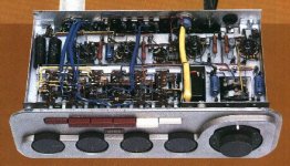
this is a pretty nice layout I think it's a Gretsch-Valco
Very interesting! No board at all---just terminal strips. Maybe a little more difficult to locate parts but certainly little chance of inadvertent shorts.
No board, terminal strips, that is what point to point means.
That is not fair. As a warranty repair station for many brands, I found more bad solder joints on Fender hand wires tube socket connections than I did on their pc boards. A solder joint can be defective on any format of construction.
Overheating a circuit board while soldering is a problem of the technician, not the board. Use a CLEAN and HOT iron to quickly heat the joint and flow GOOD solder into it. Takes a second or two and only lifts pads if the board is ultra cheap or if the tech is inexperienced.
Interference from feedback and heaters, and crosstalk in general, is a matter of poor layout design. A zillion home builders of tube amps have had problems with grid wires getting too close to output wires, causing parasitic oscillations and other issues. A classic is ticking from the tremolo oscillator getting into the signal path due to poor lead dress. Same with heaters, far more amps have heater noise in hand wired chassis than in printed circuit board amps.
resistors do get hot, in many places, and can indeed cause problems on a circuit board. But in cases where it is a serious issue, it is a design mistake on the board engineer's part. Using too small a resistor (wattage) is a major cause. Instead of a composition resistor, a nice wire wound up on posts will get you out of most of those problems.
My point being, the problems listed can occur in ANY format.
From my experience, pcb has always tons of problems:
- local resistor heat up
- bad solder connection
- over-heating while soldering
- interference with feedback - heathers (tube amps) and input stages
That is not fair. As a warranty repair station for many brands, I found more bad solder joints on Fender hand wires tube socket connections than I did on their pc boards. A solder joint can be defective on any format of construction.
Overheating a circuit board while soldering is a problem of the technician, not the board. Use a CLEAN and HOT iron to quickly heat the joint and flow GOOD solder into it. Takes a second or two and only lifts pads if the board is ultra cheap or if the tech is inexperienced.
Interference from feedback and heaters, and crosstalk in general, is a matter of poor layout design. A zillion home builders of tube amps have had problems with grid wires getting too close to output wires, causing parasitic oscillations and other issues. A classic is ticking from the tremolo oscillator getting into the signal path due to poor lead dress. Same with heaters, far more amps have heater noise in hand wired chassis than in printed circuit board amps.
resistors do get hot, in many places, and can indeed cause problems on a circuit board. But in cases where it is a serious issue, it is a design mistake on the board engineer's part. Using too small a resistor (wattage) is a major cause. Instead of a composition resistor, a nice wire wound up on posts will get you out of most of those problems.
My point being, the problems listed can occur in ANY format.
Bigger fatter round wires sound better, heat dissipation is better, components of critical .
some evidence exists that validates, we for example now know that the widely used skin depth equations are incorrect.
That is why facilities sensitive to emp had to be abandoned and rebuilt.
No board, terminal strips, that is what point to point means.
That is not fair. As a warranty repair station for many brands, I found more bad solder joints on Fender hand wires tube socket connections than I did on their pc boards. A solder joint can be defective on any format of construction.
Overheating a circuit board while soldering is a problem of the technician, not the board. Use a CLEAN and HOT iron to quickly heat the joint and flow GOOD solder into it. Takes a second or two and only lifts pads if the board is ultra cheap or if the tech is inexperienced.
Interference from feedback and heaters, and crosstalk in general, is a matter of poor layout design. A zillion home builders of tube amps have had problems with grid wires getting too close to output wires, causing parasitic oscillations and other issues. A classic is ticking from the tremolo oscillator getting into the signal path due to poor lead dress. Same with heaters, far more amps have heater noise in hand wired chassis than in printed circuit board amps.
resistors do get hot, in many places, and can indeed cause problems on a circuit board. But in cases where it is a serious issue, it is a design mistake on the board engineer's part. Using too small a resistor (wattage) is a major cause. Instead of a composition resistor, a nice wire wound up on posts will get you out of most of those problems.
My point being, the problems listed can occur in ANY format.
My experience points to totally the opposite. There is just no comparison possible with what you can achieve with PTP. PCB are the worst thing possible for heat dissipation period!
There so much you can do on a flat 1 mm board , different path cross very close to one another, wires are flatten out and solder connection are always poor. I solder tons of pcb and it is always a TINY portion of the component lead that really bounds and touches the pcb inlet of through-hole or pad, the solder has to do everything.
Never heard of the skin depth equation. 😕
yes in the 32/64 digital bit relm 4-16 layer pcbs are of course necessary.
i had analog front ends/sigma-delta a/d converters on the boards but were really two different projects.
An analog ground star and a digital ground plane are required.
pCBs are necessary for sure there .
But on hi-fi commercial and pro audio not really.
ask yourself who's problem does the PCBoard solve ?
It solves the problem of making a consistent quality product at a price the customer can afford. A very small market segment can afford hand built amplifiers. SO in a sense it solves the problem for both maker and buyer.
Sure heat is bad for circuit boards, that is why good engineering accommodates that. Anyone can design a bad board. Got cheap zener power supplies and dropping resistors overheat the board? Do what they do with transistors, mount power resistors on a heat sink (the chassis).
Oh look up "skin effect", I would assert it isn't much of an issue with currents and voltages we use in guitar amps. In all the amps I have serviced over the years, I rarely see pc traces heating up unless there is a circuit fault. Usually the heat is made by components soldered to the board. Dropping resistors on the Fender Hot Rod series as an example. That was a design shortcoming.
to dotneck335 post #27:
I can't remember exactly but I believe it was a 15H that was lying around. They are not so expensive and easy to find.
I like to confirm the post #31 and 35 by Enzo.
It is the knowledge and experiance of the design engineer that gives a certain result for a certain price that finally the end user has to pay.
Everything can be made better except ONE thing; Your wallet.
Be it ptp or pcb.
I have to laugh at all these postings where details of no real imporatance are discussed in more details then in an electronics factory lab (I worked there for more then 10 years...)
At the end of the day I only want to play or listen to music, to the feeling it gives to me, to what it does to me. If it's bit out of tune, some side noises or the singer has glasse, I do not care.
That's all what music is about, don't you think?
to Tarzan:
Thanks!!--I did find this choke for ~$28 at Antique Electronic Supply:
https://www.tubesandmore.com/products/P-T159M
Thanks!!--I did find this choke for ~$28 at Antique Electronic Supply:
https://www.tubesandmore.com/products/P-T159M
I think the biggest reason for PCBs is an extreme reduction in manufacturing costs.
A minimum wage US worker can assemble maybe 100 or more amps using a cheap Chinese component populated board in an 8 hour shift.
A highly skilled technician, a much more expensive worker, might be lucky to assemble a few amps with Point to Point wiring on the same 8 hour shift.
It is easy to see why almost all high volume amp manufacturers go with PCBs.
Circuit boards are consistent and reliable. There won;t be any wiring errors and the layout is etched in copper, no problems with lead dress.
- Status
- Not open for further replies.
- Home
- Live Sound
- Instruments and Amps
- Point-to-point wiring vs. PCBs