After much time spent on pcb layout for tubes, i'm not sure its the way to go.
Even with a 92mil board the Top to Bottom parasitic coupling may be noticeable.
So Im rethinking the use of pcb sockets etc. Its ok on ancillary and powersupply but not on gain stages.
Even with a 92mil board the Top to Bottom parasitic coupling may be noticeable.
So Im rethinking the use of pcb sockets etc. Its ok on ancillary and powersupply but not on gain stages.
In the early 1990s I spent a few "interesting" months fixing an incredibly average PCB design. The engineer who gave birth to this abortion had ignored if not all, then at least most, of PCB Design 101.
I ended up redesigning and building the thing with wire wrap. The military spec version of point to point.
The only reason I did this is that I had one week to get the thing into service.
The issue that led to this was poor layout leading to crosstalk and ringing in audio areas. If this were a pure digital circuit nobody would have cared. It was analogue and hash at -60dB was a big deal.
Once you go to the expense of point to point in The modern age, the cost drives you to adding the care factor in layout.
That said, nothing comes close to the repeatability of pcb layout. Once it is right, you are set.
Last edited:
Interesting thread....
any advisories necessary for converting a schematic into a point to point rather than use a pcb design?
any advisories necessary for converting a schematic into a point to point rather than use a pcb design?
Interesting thread....
any advisories necessary for converting a schematic into a point to point rather than use a pcb design?
Still working on a solution, maybe a partial hard wire and partial pcb.
I have a slight disability with hands so 100% wire is not possible. Can do pcb assy but not too much free air soldering.
A production environment is even tougher.
I looked at Dynaco's original tape layout on the ST70 driver.
They used large trace spacings and free style tape to use pcb.
So a modern tube board will be very large anyway to get the space distance. Its almost a wash there.
I wish the ceramic - silver terminal strips were still in production.
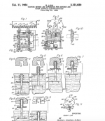
Here is the expired Tektronix patent. Yes I've seen the partsconnxton site.
https://www.google.com/patents/US3121020
-
Attachments
Keep input (high gain) traces away from and non-parallel to high current outputs.Interesting thread....
any advisories necessary for converting a schematic into a point to point rather than use a pcb design?
Flow the input on one end of card, output on the other end.
If 2 dimensions would violate first rule, use the third dimension to achieve it.
An inch spacing to parallel wires adds inductance and can prevent oscillation.
See my point-to-point version of this PCB amp board in post 212:
http://www.diyaudio.com/forums/solid-state/236256-retro-amp-50w-single-supply-22.html
On one 12 cm long high gain input run, I used a 8 turn coil near the input to prevent RF pickup when the cover was off the amp.
Generally, I find that true P2P can cause a lot of problems (crosstalk, oscillation, hum) except in the case of very simple circuits and/or a very skilled P2P circuit builder.
Personally, I prefer turret board both for prototypes and small scale production. Second after that, for prototypes, two or three parallel long rows of tag strips which provides for a similar tidy layout to turret board.
Robert Aiken of Aiken Amps has an interesting hybrid approach used for his "boutique" guitar amps, seen at the end of this article on the PCB vs hand wired topic - http://www.aikenamps.com/index.php/is-point-to-point-better-than-pcb
Sent from my phone. Please excuse any typpos.
Robert Aiken of Aiken Amps has an interesting hybrid approach used for his "boutique" guitar amps, seen at the end of this article on the PCB vs hand wired topic - http://www.aikenamps.com/index.php/is-point-to-point-better-than-pcb
I should have said Randall Aiken. Aiken is a very knowledgeable engineer.
Grid leak bias, can it be (correctly) done on a pcb?
Humidity absorption characteristics of frX? RH in my area is quite high.
Still trying to see if its a dealbreaker. Maybe Tfe pcb or bakelite with glypt cover.
Humidity absorption characteristics of frX? RH in my area is quite high.
Still trying to see if its a dealbreaker. Maybe Tfe pcb or bakelite with glypt cover.
New to this discussion but interesting points along the way. I can't say one way whether or not I have a side in the battle, but have gathered a few things along the way.
I have always considered some PTP wiring was done because of small runs or limited resources. Today it would seem "doing it the hard way" is boutique. I see lots of people woodworking with hand tools, and frowning on anyone who produces something equally impressive because they "used machines". There is something artisanal about PTP that is lost with PCB's.
The arcade folk I deal with pointed out to me that PCB's for the old games will not last forever and eventually they will be useless without replacing the board with something else. Perhaps this is something to consider - older PCB's and newer ones probably arent the same - and the older ones probably wouldn't hold up too well to touring and constant repairs over time. Point to Point simply has better longevity and serviceability over Printed Circuit Boards if my thinking is correct. This could be where lots of bias lies IMO.
Also, it's like any industry dealing with quality of reproduction... there's always something that will be marketed as being better than the competition for any and all reasons... even if some are complete hogwash. Heck, I've seen cable debates over on the music forums... nobody is immune! haha
This PWB going on a boat or something? The year in Houston I tried living without air conditioning, the walls molded. That was off Almeda-Genoa. You've got to A/C some in Houston to keep the humidity down. Same as here in the Ohio valley, I A/C to 80 or 78.Grid leak bias, can it be (correctly) done on a pcb?
Humidity absorption characteristics of frX? RH in my area is quite high.
The dynaco PAS2 & ST70 survived that year without mold. They have paper/chemical PWB. The 8 hours a day I ran the things, 12 on weekends, must have kept the mold spores dead.
I build PTP on Nema CE board, easier on the drill than glass reinforced board. Trade name textolite/micarta/garolite. From mcmasters. I use 1/16" thick board. I tried polycarbonate, but solder melts it and sticks to it making bridges between pins. things bigger than 0.1" pitch of DIP packages may be okay on polycarbonate.
Last edited:
I've seen good quality substrate material showing some conductivity, just here in Toronto. It certainly wouldn't have been good for grid leak bias circuits, along with most other tube amp circuits. So we rejected several samples from the supplier.
Sent from my phone. Please excuse any typpos.
Sent from my phone. Please excuse any typpos.
- Status
- Not open for further replies.
- Home
- Live Sound
- Instruments and Amps
- Point-to-point wiring vs. PCBs