Depending on whether it is 10x (+20dB) or 1/10th (-10dB).
Jan
Should of course be 1/10th = -20dB...
Jan
My sound card needs a new op amp. The OAs en situe are NJM4580C judging from the markings. I can't find these but the NJM4580 seem to be available. Link to New Japan Radio website.
These look to be the same in every way except supply (non C version has wider supply range), ft and noise. With respect to the latter, the non-C has noise described as "0.8μVrms typ." while the C version has "5nV/√Hz typ. at f=1kHz". Is there a way to compare these?
Likely a NE5532 would be a good fit here. The non-C datasheet has a voltage noise graph on page 3.
Samuel
Thanks. Seems like the non-C version has better noise which is good given its availability. (It's lower than 5n at 1kHz.) Seems lower than the NE5532 also. I found this article which helps translate the noise figure into an RMS equivalent for a specific frequency range.
Noise Figure & Other Stuff
I was originally hoping to use an LM4562 but the package is smaller than SOIC-8. Looks more like SOP-8.
Noise Figure & Other Stuff
I was originally hoping to use an LM4562 but the package is smaller than SOIC-8. Looks more like SOP-8.
Last edited:
Ti's 4562 datasheet dated 2013 shows three package versions:
LMC To99 metal
P 0.1" pitch dip
M 0.05" pitch dip (=SOIC)
LMC To99 metal
P 0.1" pitch dip
M 0.05" pitch dip (=SOIC)
I have repaired my sound card - well I have one good channel which is all I need for measurement with ARTA. (I seem to have a volume problem with the other channel which I will investigate at some later point.)
Question for Samuel: is the shorted input noise profile you see in post 47 what you'd expect from the amplifier? (A straight loopback of the sound card produces a very 'clean' THD+N profile.) (The amplifier is powered by 9V batteries.)
Question for Samuel: is the shorted input noise profile you see in post 47 what you'd expect from the amplifier? (A straight loopback of the sound card produces a very 'clean' THD+N profile.) (The amplifier is powered by 9V batteries.)
Is the shorted input noise profile you see in post 46 what you'd expect from the amplifier?
In which respect?
Samuel
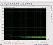
I mean all the peaks in the FFT. Below is the image from the previous post (preamp shorted versus 1k resistor). The newer thumbnail image shows the preamp shorted (yellow) versus the sound card looped back (green). I left the preamp gain setting in ARTA unchanged for the latter so the two align better. (All 32 linear averages.)
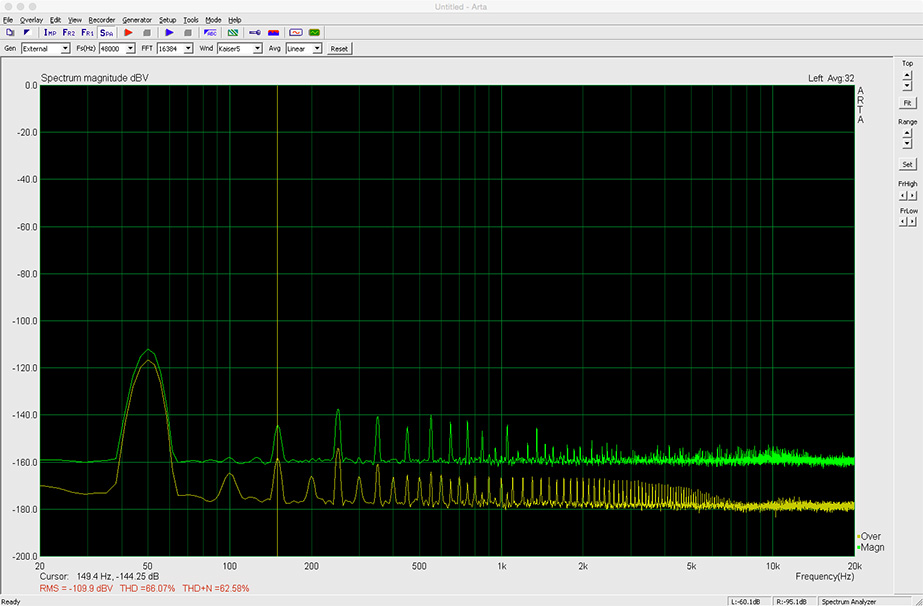
I presume the peaks in the yellow ft result from preamp noise or something else in my cabling to the sound card. I'm just wondering if this sort of noise floor is to be expected for this preamp or whether it is an indication that I have done something wrong.
Also, has anyone else built their boards yet?
Attachments
What you see is hum (mains power interference). Can you run a measurement set with the input of the sound card shorted (not a loop back!), and then with the preamp connected and its input shorted? This will indicate if the hum is picked up by the preamp, or a "feature" of the sound card.
Samuel
Samuel
The embedded pic above (not the thumbnail) had, as its yellow trace, the preamp input shorted (connected to sound card) but I did all the measurements again for a better side-by-side comparison.
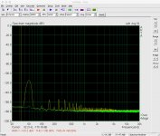
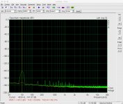
The first pic below shows - yellow trace - the cable to the balanced input of the sound card shorted (i.e. the clips at the preamp end simply connected together). The green trace is with the unpowered preamp connected to the cable with its input shorted. The second pic is the same but with the preamp powered. It suggests to me that neither the sound card or the cable is the source of the noise.
These images show a better noise floor than the previous images, but still a lot of interference/noise. I guess the next step is to put the preamp in a metal box, but I'm surprised it acts as such a good antenna.
Attachments
Aluminium conductive enough?
Yes, although pure silver would be better. 😉
Samuel
😉
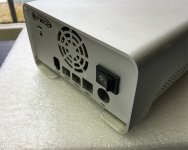
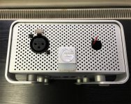
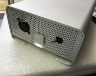
Hopefully this will be better. I found an old Firewire drive. I thought the G was poetic (and it had a built in LED and switch). Need to purchase a BNC jack for the input.
Hopefully this will be better. I found an old Firewire drive. I thought the G was poetic (and it had a built in LED and switch). Need to purchase a BNC jack for the input.
Attachments
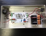
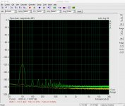
Ok some progress. My BNC connector arrived. Pic 1 shows the result when I short the input connector on the board itself (and then assemble the enclosure). The second pic is when I short the BNC chassis connector. (The yellow trace is the sound card shorted at the XLR/amp end of the balanced cable.) Initially I had problems because the board mounting holes aren't isolated from the circuit and I had used metal standoffs - cold/GND of the input BNC was therefore connected to the chassis.
I had planned to use a set of these BNC-alligator clip leads
DT10 EasySync | Mouser
to connect to a DUT. However, if I short this lead and look at the results in ARTA they're not pretty. Clearly I need a shorter lead and likely some means of shielding the DUT as well.
I had planned to use a set of these BNC-alligator clip leads
DT10 EasySync | Mouser
to connect to a DUT. However, if I short this lead and look at the results in ARTA they're not pretty. Clearly I need a shorter lead and likely some means of shielding the DUT as well.
Attachments


Ok some progress. My BNC connector arrived. Pic 1 shows the result when I short the input connector on the board itself (and then assemble the enclosure). The second pic is when I short the BNC chassis connector. (The yellow trace is the sound card shorted at the XLR/amp end of the balanced cable.) Initially I had problems because the board mounting holes aren't isolated from the circuit and I had used metal standoffs - cold/GND of the input BNC was therefore connected to the chassis.
I had planned to use a set of these BNC-alligator clip leads
DT10 EasySync | Mouser
to connect to a DUT. However, if I short this lead and look at the results in ARTA they're not pretty. Clearly I need a shorter lead and likely some means of shielding the DUT as well.
It looks like you got 3nV/rtHz @20Hz (assuming 10dB/decade, this maps to about 4.2nV/rtHz @ 10Hz) which is pretty good for a Jfet low noise stage.
I was always wondering how Mr. Groner got 1nV/rtHz @10Hz. This, and the incredible low noise corner frequency he got look to me like out of the reality realm for Jfets (and not only the 8xBF862). Perhaps he would care to jump in and explain?
I'm thinking it may be better to use another XLR connector rather than the BNC. At least then the input cable shielding will connect to the enclosure. It won't be connected at the other end but perhaps the Faraday cage helps. Do people think crocodile clips are still the most practical termination for the other end?
Looking good!
I'll need to check next week but I think I have shorted everything together (chassis, input connector and PCB mounting holes) in my implementation.
How did you arrive at this number?
I'm not sure what sort of reply you're hoping for; as far as I know, all details of relevance are given in the article. So your question would need to be more specific.
Samuel
Initially I had problems because the board mounting holes aren't isolated from the circuit and I had used metal standoffs - cold/GND of the input BNC was therefore connected to the chassis.
I'll need to check next week but I think I have shorted everything together (chassis, input connector and PCB mounting holes) in my implementation.
It looks like you got 3 nV/rtHz @20 Hz (assuming 10 dB/decade, this maps to about 4.2 nV/rtHz @ 10 Hz) which is pretty good for a Jfet low noise stage.
How did you arrive at this number?
I was always wondering how Mr. Groner got 1 nV/rtHz @10 Hz. This, and the incredible low noise corner frequency he got look to me like out of the reality realm for Jfets (and not only the 8x BF862). Perhaps he would care to jump in and explain?
I'm not sure what sort of reply you're hoping for; as far as I know, all details of relevance are given in the article. So your question would need to be more specific.
Samuel
I'll need to check next week but I think I have shorted everything together (chassis, input connector and PCB mounting holes) in my implementation.
But then "signal ground" (input) is connected to the balanced output cable shield...
- Home
- Design & Build
- Equipment & Tools
- Groner's Low noise measurement amp from Linear Audio vol 3 - spare boards?