Demian,
I think I will turf the PLC network extender. Looks like it's more trouble than it's worth.
I think I will turf the PLC network extender. Looks like it's more trouble than it's worth.
You mention "tube gear" ? Bad native PSRR ?
We had this discussion in the solid state thread. The member was trying to filter
up to 100Mhz on his DC , with a great increase in the complexity of his PS.
This DC was powering a symmetric amp with known >1Mhz bandwidth.
I said this limited bandwidth ... plus the audio input R/C , would naturally negate
anything above 1mhz.
Still , I don't want to see it. It is cheap to use old PC filter common mode parts.
(below 1/2)
Just to show it - (below 3/4) , are the major culprits (cheap Asian knockoff supplies).
Believe it or not , those were UL listed and in OEM PC's. You think an
unfiltered CFL is bad ..... plug in one of those 300W units.
My Corsair 600W unit has 2 C/L/C's in series. You get what you pay for.
OS
Mine is generally like what you sohwed in the B/W as No.1, only mine seems to more like the Corsair you mention later on. (C/L/C/L/C). As you say, it does work as advertised without fail. Nevertheless, in some cases it's astounding, in other case just barely heard improvements. Like I said, do not buy unless you can try it out first.
The mention of tube gear is simply a statistically proven note from my own experience with my own and other peoples' gear tests. Why is another story altogether, but of course, here too not all tube gear is the same, so try before buy still holds as an ironclad recommendation.
The purpose of mains filters on most equipment is to meet EMC regulations by preventing the equipment from radiating back along the AC supply. Many cheap pc power supplies are built and tested to do this correctly, then in production they simply don't fit the filter parts to save a few bucks. You will see the relevant part of the pcb populated with just a wire link or two...
As for MOVs etc, given that they are effectively inert except in the rare presence of a transient, what is the alleged mechanism for them being "audible"?
As for MOVs etc, given that they are effectively inert except in the rare presence of a transient, what is the alleged mechanism for them being "audible"?
A ham friend of mine is able to produce a KW on 144 MHz from his car.
He can toggle the street lights in the Schlangenbader Tunnel (in Berlin)
and approaching the car with a gas discharge lamp in your hand makes you
look like Darth Vader with his light saber.
Someone I know used to do EME, he had a 15 foot dish aimed at the horizon fed with 400W at 1296MHz... The ERP must have been.. a lot! TV sets in the line of path used to just go blank...
The purpose of mains filters on most equipment is to meet EMC regulations by preventing the equipment from radiating back along the AC supply.
Goes both ways. Luckily filters with lots of insertion loss one way and none the other are quite challenging. I would certainly rather a filtered IEC connector on each piece of equipment than a central filter unit. Not as good as rolling your own, but quick and gives you peace of mind.
Of course some DIYers prefer a power supply project with a low PSRR ultraminimalist amplifier attached. For them at least 3 large metal boxes and many layers of filtering are required to keep things nice for their handful of carefully selected components.
> Someone I know used to do EME, he had a 15 foot dish aimed at the horizon
> fed with 400W at 1296MHz... The ERP must have been.. a lot! TV sets in the
> line of path used to just go blank...
We did that on 144 and esp. 432 MHz, but had free sight to the horizon in nearly all directions
Our masts stood on the roof of the main building of the technical univ. in Berlin. It's fun to hear
your own echoes after 2.5 seconds.
Path attenuation is some 230 dB IIRC depending on frequency.
Still wanted: dish > 3 meters, for 10 GHz, maybe 24 GHz.
Last edited:
As for MOVs etc, given that they are effectively inert except in the rare presence of a transient, what is the alleged mechanism for them being "audible"?
Perhaps the circuit in which John Curl found the leakage current of MOVs to be audible, was NOT the AC mains side of a linear power supply's transformer. Maybe he's talking about MOVs between signal and ground, perhaps in a 70 volt public address system or some such. Perhaps gas discharge tubes are preferable to MOVs in this not-AC-mains application.
Why use a MOV and where is the best place for it?
Obviously for protection but of what?
One usually does the ring voltage test to simulate/test for such a AC line disturbance.
I recall the ballast mfg I worked for used MOV's in the electronic fluorescent ballasts.
A few were failing in the field, so we took them apart, yes asphalt tar filled, fun job for the juniors 🙂
The MOV's were toast and took out the fusing element, a fusible resistor to save some $.
I suggested, just get rid of the MOV's, if they conduct, then blow the fuse, the ballast is garbage as it is.
People seem to use MOV's out of habit and not follow up on there usefulness.
If you do not like MOV's, then there are othe roptions if you need protection of your circuits.
The purpose of mains filters on most equipment is to meet EMC regulations by preventing the equipment from radiating back along the AC supply.
I had noise issues with a LED floodlight in my lab. I put a mains filter right at the light, in reverse direction: the filter mains connection was at the light, and the load side was connected to the mains cord. Worked like a charm - you just have to remember that source and victim are interchanged. 😉
Jan
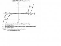
Attached is the Data from the earlier GE MOV's. Note the tolerances. So a MOV to this standard rated for 150 VAC RMS would have some that were still in tolerance begin to conduct on each cycle if the line voltage was a legal (For the US) 127 VRMS.
At my house the AC distribution is 13KV stepped down by an auto transformer to 120-120. The "Neutral" lead is also called the "Grounded Conductor" not to be confused with the safety ground.
At my shop there are three transformers used to supply my three phase nominal 208 volts. However as there are also residences fed from two of the lines they run the lines at 220. This gives me a "120" volt outlet at 127 VRMS.
Now as mentioned many times the maximum sag recommended is 5% so a 120 volt 100 amp service is allowed to sag by 6 volts or have a power station to circuit breaker box line impedance of .06 ohms. The loss from the circuit breaker is similar. So the AC line impedance is typically under .1 ohms. I have a collection of IEC cords and the champion bad one is labelled as 16 gauge UL listed and made in ... It has a resistance just above .5 ohms. (22 gauge-ish inside, lots of plastic outside. Yes fake UL label.)
In most of my measurements the AC current draw duty cycle is around 30% very rarely approaching 10%. So for a nominal current draw of 1 amp at the 10 % duty cycle that would be a 5 volt drop. On a preamp level device I would expect no effect as that would still put the dropped voltage in line with an allowable low voltage. However on a power amplifier with a 3 amp draw the loss might show up as significant. So a real power cord might make a difference.
However most of the premium power cords I have paid any attention to do not have significant resistance. What they do have is more high frequency attenuation, either by adding a shield or some other technique.
Using a power line filter of the Corcom variety does increase the line resistance and many of them do inject a small current into the chassis. So my preference is not to use them but design the power supply to reject line noise.
Most equipment power transformers are used in slight saturation to improve the apparent regulation. This combined with the rectification harmonics creates a very nice series of harmonics that drop at 3 dB per octave and go through the entire audio range. As our hearing is most sensitive in the 3,000 - 6,000 hertz range, power line noise is often perceived as a masking of the midrange.
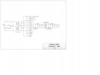
I did post a preliminary power supply deign just a bit back. (Also Attached.) note the use of out of phase windings combined at DC to reduce EMI transfer.
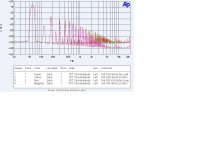
The last image is of the line distortion due to just a transformer.
At my house the AC distribution is 13KV stepped down by an auto transformer to 120-120. The "Neutral" lead is also called the "Grounded Conductor" not to be confused with the safety ground.
At my shop there are three transformers used to supply my three phase nominal 208 volts. However as there are also residences fed from two of the lines they run the lines at 220. This gives me a "120" volt outlet at 127 VRMS.
Now as mentioned many times the maximum sag recommended is 5% so a 120 volt 100 amp service is allowed to sag by 6 volts or have a power station to circuit breaker box line impedance of .06 ohms. The loss from the circuit breaker is similar. So the AC line impedance is typically under .1 ohms. I have a collection of IEC cords and the champion bad one is labelled as 16 gauge UL listed and made in ... It has a resistance just above .5 ohms. (22 gauge-ish inside, lots of plastic outside. Yes fake UL label.)
In most of my measurements the AC current draw duty cycle is around 30% very rarely approaching 10%. So for a nominal current draw of 1 amp at the 10 % duty cycle that would be a 5 volt drop. On a preamp level device I would expect no effect as that would still put the dropped voltage in line with an allowable low voltage. However on a power amplifier with a 3 amp draw the loss might show up as significant. So a real power cord might make a difference.
However most of the premium power cords I have paid any attention to do not have significant resistance. What they do have is more high frequency attenuation, either by adding a shield or some other technique.
Using a power line filter of the Corcom variety does increase the line resistance and many of them do inject a small current into the chassis. So my preference is not to use them but design the power supply to reject line noise.
Most equipment power transformers are used in slight saturation to improve the apparent regulation. This combined with the rectification harmonics creates a very nice series of harmonics that drop at 3 dB per octave and go through the entire audio range. As our hearing is most sensitive in the 3,000 - 6,000 hertz range, power line noise is often perceived as a masking of the midrange.
I did post a preliminary power supply deign just a bit back. (Also Attached.) note the use of out of phase windings combined at DC to reduce EMI transfer.
The last image is of the line distortion due to just a transformer.
Attachments
Even more educational is when you start a paper and analysis to make one point.... and then discover in the effort that the point was entirely incorrect! Math and real scientific method can be humbling things when applied.
More than once.
At my shop there are three transformers used to supply my three phase nominal 208 volts. However as there are also residences fed from two of the lines they run the lines at 220. This gives me a "120" volt outlet at 127 VRMS.
.
Oh to have those tolerances. we are 230V +10%/-6% . Currently I seem to be at 250V, but can't be sure as don't have a calibrated meter so just trusting the AC range on my cheapy DVM. Last house was 210V well out of spec but they did nothing about it. My old radford valve amp has mains taps from 210 to 250v sadly modern stuff doesn't.
holy hell, that's not far off the kind of mains supply variation I saw in Shanghai - 190VAC on some occasions and up at 230 on others.
And compromise is the B1tch.
OS
Logic and compromise = trade off in my book.
Two of the hardest things to reconcile in life
🙂
I've used MOV's very successfully on the mains input side to quench transients on all sorts of products - audio included.
In my earlier days, I worked at an industrial instrumentation company. We had a networking product and used GDD's extensively for transient protection - one from each line (it was a differential signal transformer coupled for isolation) to ground in the line side. Very rugged product that only failed on rare occasions when it took a lightening strike. This was Africa - par for the course in summer.
In my earlier days, I worked at an industrial instrumentation company. We had a networking product and used GDD's extensively for transient protection - one from each line (it was a differential signal transformer coupled for isolation) to ground in the line side. Very rugged product that only failed on rare occasions when it took a lightening strike. This was Africa - par for the course in summer.
Regarding JC comment and Demians reply regarding MOV and GDT for protection;
The Gas Discharge Tube (GDT) has nill capacitance across the ac line. Whereas, in its off state or high Z state, the MOV has a moderately large non-linear C across the ac line. The GDT will continue to conduct even after the high voltage transient has gone away. It blows a fuse. The MOV goes to high Z state after the high voltage transient is gone. The MOV doesnt blow a fuse when a transient hits it.
The better approach for protection without a non-linear C across the line is:
Place the GDT and a low voltage MOV in series. Select the total voltage of the GDT and MOV to give the level of protection needed across the ac line. There will be no C across the ac line and when the HV transient does cause the GDT and MOV to conduct, the MOV will extinguish the GDT after the transient has passed by going to its high Z state. Thus resetting the GDT to its high Z state (non-conducting). No blown fuses and no non-linear C on the ac line.
THx-RNMarsh
Last edited:
BTW --- The new Samsung UHD (9000 series) and its companion smart 4K player are amazing. Sure the detail is even better (yes, I peeked) but its the additional bits used for colors.... it is the amazing range of newly available colors I now see that is most improved IMO.
-RNM
-RNM
Last edited:
Good idea Richard. Be sure to show that to Demian.
Thanks Demian for the operating manual on the 1500, and I hope I have not stepped on too many toes regarding MOV's. I personally use a GDT with a dedicated circuit breaker in the same box, myself, but it is a very expensive product that it goes in, and is not practical for everybody.
I'm sure that some MOV's, especially around computers is a very good and even necessary thing, but for hi end audio, I don't put them in.
- Status
- Not open for further replies.
- Home
- Member Areas
- The Lounge
- John Curl's Blowtorch preamplifier part II