I havent had a problem with the noise from generators.... but maybe could be reduced some more..... Mostly the noise problem is on the distortion analyzer side that i think needs some more attention.
THx-RNMarsh
THx-RNMarsh
A 10 uF polypropylene is affordable for the bottom frequency.
I don't think you have given a detailed set of desired specifications for your design (or at least I don't recall it), so it's difficult to be specific. In any case the distortion performance (at operating and distortion levels of interest here) of film capacitors appears to be rather erratic, with large differences between types and also specimen (40 dB and more). I'm not aware of a systematic method to select a good film capacitor short of directly measuring its distortion performance. I suggest you consider ceramic C0G too.
How do we articulate the noise performance of these oscillators?
As the oscillators we're discussing have very low distortion, they can be well described by linear superposition (sine + noise). At frequencies close to the carrier, noise from the leveling loop may show up and give unexpected sidebands. Apart from this, the noise is basically that from the resistors, opamps and the multiplier, so easily described with standard small-signal noise analysis methods.
THD+N and standard FFT-based measurements are only sensitive to amplitude noise, so phase noise is, unless extreme, no concern (in any case it would have the same power as amplitude noise except close to the carrier, where amplitude noise is reduced by the leveling loop while phase noise rises without limit). Measuring the oscillator output and plotting a spectral analysis in V/rtHz would be a very meaningful measurement for me.
Samuel
...[No] detailed set of desired specifications... so it's difficult to be specific.
Approximately what you proposed as ambitious but achievable in post #627😉
If I can do better without too much cost then I would be happy, of course.
In any case the distortion performance (at ... levels of interest here) of film capacitors appears to be rather erratic
Yes, I can use NP0 almost exclusively, now they are available as MLCC up to 1 uF.
It's just that last decade, and industrial polypropylene looks adequate.
Rated at 450 V a.c. so thick film and thus low electric field when used at oscillator levels.
Only problem is the end connections to metalized films.
I expect that the heavy currents required in industrial applications will mean a decent low impedance connection.
I believe the maximum dV/dt is a clue to this.
There are also some hybrid metalized film + foil that look excellent
Cyril Bateman's results for polypropylene were pretty decent, and perhaps the lowest decade can risk a little extra distortion.
Seem reasonable?
Or I can just suffer the cost and buy 20 expensive 1 uF NP0 MLCC.
Best wishes
David
Last edited:
Approximately what you proposed as ambitious but achievable in post #627.
Yes, for these specifications you should get away with standard film caps if you run them at modest AC voltage. On the other hand, you could realize these specs also with low capacitance (say 300 nF for the lowest range) and a higher AC voltage.
Samuel
... for everyone to ponder.
...So what is the bandwidth of an undamped SVF if the gain at resonance is 60dB and GBP is 24MHz?
Hi (other) Dave
I am not sure I understand your question.
The literal answer is that if the gain at resonance is 1000 then the bandwidth will be, near as dammit, the oscillator frequency / 1000.
Are you actually interested in how the GBP affects the gain at resonance?
Best wishes
David
Hi (other) Dave
I am not sure I understand your question.
The literal answer is that if the gain at resonance is 1000 then the bandwidth will be, near as dammit, the oscillator frequency / 1000.
Are you actually interested in how the GBP affects the gain at resonance?
Best wishes
David
I'm not asking about the band pass bandwidth. I asking about how gain in a narrow bandwidth effects the band width of the amplifiers. Is it calculated the same as for a wide band amplifier. The question is related to how the bandwidth reduction if any will effect Q enhancement. Maybe it doesn't.
...about how gain in a narrow bandwidth effects the band width of the amplifiers.
I still don't understand your question, by "amplifiers" do you mean the op-amps themselves?
Is it calculated the same as for a wide band amplifier.
Could you show an example of the calculation for a wide-band amplifier so I may see what you mean?
The question is related to how the bandwidth reduction if any will effect Q enhancement. Maybe it doesn't.
I find it useful to think in terms of the Bode plot of the Return Ratio because this provides a universal and unified method of analysis.
"Q enhancement" is simply a name for the result of phase shift from upper poles.
Consider the basic SV oscillator, just the simplest loop with no internal feedback to damp or sustain oscillation, no compensation trimmers etc.
If the capacitors are low loss then the Q of this oscillator is controlled mostly by the balance of phase shift from the lower pole and upper poles of the op-amps.
The lower pole is set by the finite gain at low frequency and the upper pole(s) are set by second order effects.
If the GBP was a perfect line then neither of these effects would occur, so GBP doesn't directly enter the equations.
At least, that's as I understand it - there's always an implicit AFAIK.
Best wishes
David
Last edited:
Lets take an op amp for example. Say the GBP is 100MHz. If we arrange a circuit that gives us a gain of 1000 then the usable bandwidth of the amplifier is 100kHz. If we arrange a narrow bandwidth band pass filter circuit with the same 100MHz op amp and suppose the gain at resonance is 1000 then how does this effect the usable bandwidth of the op amp?
Lets take an op amp for example. Say the GBP is 100MHz. If we arrange a circuit that gives us a gain of 1000 then the usable bandwidth of the amplifier is 100kHz
Perhaps I still misunderstand your point but I suspect you don't conceptualize this clearly.
There is no effect on the usable bandwidth of the amplifier, it still works exactly the same.
It's just the circuit it's part of will have a bandwidth of 100 kHz because that's when the required gain hits the 100 MHz GBP limit.
It's very clear if you draw up a Bode plot.
The best presentation on this that I have seen is by Kent.>HERE<
He shows how much easier the Bode plot analysis is compared to some tedious math.
You can try to analyse the specific circuit but the particular currents and potentials are almost irrelevant.
The behavior is set by the gain curves, whatever the internal details.
The true master of the subject is R D Middlebrook.
If you haven't already seen his work then I recommend a quick search and then an extensive read.
He put a lot of his private course material, previously for-profit, on the web before his death.
I try very hard to use his approach to see how a circuit behaves, with appropriate plots, usually Bode but there are others.
Of course, different people have different ways to think about problems so I try to understand different perspectives.
But I have found Middlebrook really helpful, think I start to understand oscillators.
Best wishes
David
Last edited:
noise
Obviously. But even for THD-N meters noise does matter, in particular in case of very low THD levels.
Cheers, E.
Might be for THD+N meters. Then it could matter?
-RNM
Obviously. But even for THD-N meters noise does matter, in particular in case of very low THD levels.
Cheers, E.
Obviously. But even for THD-N meters noise does matter, in particular in case of very low THD levels.
Cheers, E.
I don't think anyone was talking about that large a tradeoff at a 1Hz BW -150dB is ~32 nV/rt-Hz
Just for painful clarity you mean -150 dBV so 32 nV rt/Hz for a 1V signal. For reference 5 nV rt/Hz is typical on the better analyzers. Lots of headroom there. It's different in a 30 KHZ bandwidth, a calculation I can't do in my head.
Sent from my SGH-M919 using Tapatalk
Sent from my SGH-M919 using Tapatalk
Just for painful clarity you mean -150 dBV so 32 nV rt/Hz for a 1V signal. For reference 5 nV rt/Hz is typical on the better analyzers. Lots of headroom there. It's different in a 30 KHZ bandwidth, a calculation I can't do in my head.
Sent from my SGH-M919 using Tapatalk
Yes, I'm not that fond of THD+N graphs, frequently it is useful to see real distortion at low output level. I suspect they are popular because of what they hide rather than show.
Isn't THD + N just for economical reasons. It's more complex and costly to do THD if FFT is not available. As you pointed out Scott the noise of a DUT can be measured directly.
Isn't THD + N just for economical reasons. It's more complex and costly to do THD if FFT is not available. As you pointed out Scott the noise of a DUT can be measured directly.
THD+N is done largely because analog THD analyzers generally just did a very good job of notching out the fundamental, leaving THD and noise to be measured. Back then, analog spectrum analyzers were very expensive, so spectral anaysis of individual harmenics, and then power summing them, was costly and tedious. When PC processing with enough power to do good DSP and sound cards became good enough, that is when measuring THD by itself became much more customary.
The problem with THD+N is that one inevitably finds it rising as measured power of a power amplifier goes down. One cannot usually tell whether the measurement is reflecting noise or crossover distortion.
Cheers,
Bob
Hi Dave,
Here is a video providing the math for active filter Q enhancement.
Hope you can cut through the accent.
https://www.youtube.com/watch?v=0BKMoJ3BTdY
There is a dependency on GB.
Here is a video providing the math for active filter Q enhancement.
Hope you can cut through the accent.
https://www.youtube.com/watch?v=0BKMoJ3BTdY
There is a dependency on GB.
THD+N is done largely because analog THD analyzers generally just did a very good job of notching out the fundamental, leaving THD and noise to be measured. Back then, analog spectrum analyzers were very expensive, so spectral anaysis of individual harmenics, and then power summing them, was costly and tedious. When PC processing with enough power to do good DSP and sound cards became good enough, that is when measuring THD by itself became much more customary.
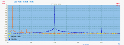
Well, to go into the real low dynamic range (> 120 dB), a tracked notch is still required. Otherwise AP could not go into this deep levels. The limitation is still given from the today's "Audio" ADC performance. But gets better and better. To have a ADC with >140dB DR, a larger sample rate >192kHz and without noise shaping rising at Fs/4. May ESS will show soon a new "Audio" ADC performance 😀
Attached is a measurement with 1kHz & 10 kHz LDO oscillator, who shows "lower" THD performance at it really is. Typical for 1kHz about -150dB and for 10kHz about -140dB.
Hp
Attachments
Last edited:
Here is a video providing the math for active filter Q enhancement...
Thanks for the link, my internet is slowish so I will watch it at the library tomorrow.
In the meantime I will think it over, always more educational to work it out than just see the answer
There is a dependency on GB.
Intuitively it feels there should be, that's partly why I was cautious.
My experience has been on audio power amps, and these don't invert.
The inversion has more consequences than just a 180 phase shift, I may have messed this part up.
But I don't think it alters too much.
Conveniently, I had used the GBP unity gain frequency as my estimate of the pole that caused extra phase.
This was because the AD797, my benchmark, does not have simple frequency/phase behavior and I wanted to be conservative.
So it doesn't actually affect my numbers.
Best wishes
David
- Home
- Design & Build
- Equipment & Tools
- Low-distortion Audio-range Oscillator