Sorry, totally overlooked.
I've simply cut a foot off the end of the stock cables, made a pigtail out of that with a female 4pin, and put a male 4pin on the headphone side. Might try some aftermarket jobs sometime however I'm normally a loudspeaker listener so its not something I have put any effort into yet.
Just only wanted to share my experience when I replaced the stock HD800 cable with a high quality one. The SQ has improved dramatically.
Just only wanted to share my experience when I replaced the stock HD800 cable with a high quality one. The SQ has improved dramatically.
Was the "high quality one" balanced or single ended? The stock cable isn't exactly bad quality either... most people upgrading cables are going from single ended to fully balanced and of course that will yield a difference...
A belated thank you to SOEKRIS for the INVERT mode.
I have now got over my fear of umanager. I felt sure I was going to mess something up while using it. Now I see that would be difficult.
It is amazing how much better many records can sound when this is correct.
Many will find that records they thought sounded a little funny can, with a change of polarity, sound very good. Especially the orchestral records but it happens just as often with pop stuff.
Again, my sincere thanks for this addition.
I would still appreciate some clarification on the ISOLATED RS232 port - where is it and how do you use it?
---------------------------------------------------------------
I see this from spikestabber:
Originally Posted by rbalu72 View Post
As per Hifiduino blog
The dam1021 has two serial interfaces:
Noise isolated TTL-level serial
RS232 serial (This is J10)
Where is noise isolated ttl-level serial port on DAM1021 Board? Can someone explain?
"It's a pair of pins on the J3 header block. See the pinout diagram."
-------------------------------------------------------------------------
Well, if there is something on J3 for this it must have a name that is unrecognizable to someone who knows nothing about RS232 ports. I have looked at the pinouts over and over, I see nothing.
Would someone explain this?
I do not, at this point, hear anything bad from using the J10 access but obsession knows no limits and I would rather use the ISOLATED one if I could.
THANKS,
Looking at J3, the pins you need are ISO RXD IN and ISO TXD OUT. You will also need a ISO GND connection.
Keep in mind that this serial port is isolated from the DAM but shares a common ground with your USB to I2S interface..
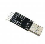
Plus, these pins are at 3.3V levels (and not RS-232 levels), assuming that the dirty side of the isolators is powered by 3.3V. So your RS-232 interface will not work. You will need a "simpler" interface, like this one: USB 2 0 to TTL UART Module Serial Converter CP2102 STC Replace Module Dteg | eBay which you should jumper for 3.3V operation.
Keep in mind that this serial port is isolated from the DAM but shares a common ground with your USB to I2S interface..
Plus, these pins are at 3.3V levels (and not RS-232 levels), assuming that the dirty side of the isolators is powered by 3.3V. So your RS-232 interface will not work. You will need a "simpler" interface, like this one: USB 2 0 to TTL UART Module Serial Converter CP2102 STC Replace Module Dteg | eBay which you should jumper for 3.3V operation.
A belated thank you to SOEKRIS for the INVERT mode.
I have now got over my fear of umanager. I felt sure I was going to mess something up while using it. Now I see that would be difficult.
It is amazing how much better many records can sound when this is correct.
Many will find that records they thought sounded a little funny can, with a change of polarity, sound very good. Especially the orchestral records but it happens just as often with pop stuff.
Again, my sincere thanks for this addition.
I would still appreciate some clarification on the ISOLATED RS232 port - where is it and how do you use it?
---------------------------------------------------------------
I see this from spikestabber:
Originally Posted by rbalu72 View Post
As per Hifiduino blog
The dam1021 has two serial interfaces:
Noise isolated TTL-level serial
RS232 serial (This is J10)
Where is noise isolated ttl-level serial port on DAM1021 Board? Can someone explain?
<SNIP>
Sent you a message on this, Rick.
Also, many thanks on confirming the 'INVERT' does reverse signal polarity... YAY!!!!!!
I just wish it was brought out to a switch instead of needing to use the RS232 interface to change it. I'll have to do a DIMDIM controller now too!
Greg in Mississippi
Thanks to you both for the help.
So far, I have found with the standard RS232 and using the BRAINBOX USB adapter (see I don't completely despise USB!) I do not hear anything wrong with leaving it connected.
I guess I now see why one of those isolators was turned the other way.
I might have removed it, since when I get going with removing stuff I find it hard to stop.
SO, if I have removed the isolator I will not have an isolated serial port, will I?
Easy enough to reinstall.
Funny how I never put two and two together - looked at those drawings too many times to not have been able to see RXC and TXD was there on BOTH!
Not quite as bad as when dimdim had to point out to me I had selected the wrong transfer rate with TERA TERM. (had 192000 fixed in my head) But, really close.
Now to give this a try.
Thanks, again.
dimdim,
You should have known when you told me to "jumper" I would have no idea what to jumper.
When you get a chance, please let me know.
Ordered an adapter.
I have all of my grounds attached at a single point and my IIS isolators are removed, could I possibly have more potential for noise with this input than the standard in your opinion?
Thanks again,
The "thing" with an isolator is mostly as I see it about ground. The grounds are completely separated. Ground differs from signal in the sense that nothing is copied over the isolator. The signals should in the case when reclocking is present on the receiving side, (as is in the DAM (happens in the pga)) be bandwidth limited to the point where signal integrity (no faults conveyed) is still maintained. By limiting the BW, HF crap can be removed. Hopefully the ground is clean on the isolated side - should be better than any laptop, rasbarry pie and what not.
So one can see that it is not possible to discuss isolators in "isolation", but as usual the context and what one wish to achieve must be understood.
//
So one can see that it is not possible to discuss isolators in "isolation", but as usual the context and what one wish to achieve must be understood.
//
Thanks, TNT.
When I wrote I was speaking of my IIS inputs, power inputs and output grounds are all connected together. No isolation of the IIS inputs.
I guess if I use the ISOLATED ground on J3 I should be OK? As good as it can get, I guess.
I am using a desktop computer which is using a better than average PS, the POWERFLOWER that gets good marks and the whole machine is running as slow as I can get it. I would like to think it is pretty quiet for a computer, not audio computer quiet (with linear supplies and such).
I was planning on supplying 5 volts of linear power to the USB device(splicing into the cable before the device. I have a REGEN which I am not using which I could insert between the computer and the device for some additional isolation from the motherboard.
So far, using the BRAINBOX USB serial adapter I am not hearing any additional spurious noise but I have found it can take some time for this noise to become audible. I figure it is part of the fatigue factor - the ear brain initially will ignore it and then it finds it annoying.
Might as well implement this as well as possible. Well, not so far as getting an INTONA. I do have my limits ...
Would dimdim's ARDUINO idea be quieter than a good PC? I know it would be nice having such a small package!
Am I assuming correctly that I can still use TERA TERM with this port?
Yes, I really am that dumb about this stuff!
Thought it might add something! Can't seem to sell the thing so always trying to find something to do with it.
How about something like this:
EVAL-CN0160-EB1Z - ANALOG DEVICES - ADUM4160, USB PERIPHERAL ISOLATOR, EVALUATION BOARD | Newark element14
Could this be better than the isolated port? One part of me wonders about having the line from the computer so close to the music inputs?
I know I will always want to be able to use umanager so it needs to be as unobtrusive as possible.
Last edited:
Found a ready made implementation: USB Isolator Protection Board Magnetic Coupling Module ADUM4160 CNC | eBay
Any speculation as to whether this would do much of anything?
You must read the description.
Any speculation as to whether this would do much of anything?
You must read the description.
dimdim,
You should have known when you told me to "jumper" I would have no idea what to jumper.
When you get a chance, please let me know.
Ordered an adapter.
Most of the time these adapters have a jumper that you can set for either 3.3V or 5V logic levels. Looking at this one, I thought I saw such a jumper, but looking at the description it looks like the 3.3V & 5V pins are voltage outputs, not voltage selection. Chances are that it's logic levels are already at 3.3V, but you should confirm that (measure it) before you connect it to the DAM.
I have all of my grounds attached at a single point and my IIS isolators are removed, could I possibly have more potential for noise with this input than the standard in your opinion?
Thanks again,
Without isolation you are at the mercy of the I2S & Serial port circuits / boards. YMMV.
Attachments
Would dimdim's ARDUINO idea be quieter than a good PC? I know it would be nice having such a small package!
Possibly.. It is very low power compared to a PC, or even an RPi. But you would have to measure the DAM to be sure. In my Arduino shield I implement a second layer of isolation, between the Arduino's serial port and the DAM's isolated port, so as to isolate the Arduino from the USB to I2S interface.
Am I assuming correctly that I can still use TERA TERM with this port?
Yes, I really am that dumb about this stuff!
Yes, your assumption is correct.
No, you are not nearly as dumb about this stuff as you believe.
dimdim,
You are very kind! Both for your generous assessment of my computer abilities and for your advice.
Turns out I did not remove the isolator for the isolated port but I still am wondering if using a USB isolator into the BRAINBOX USB/RS232 might not be even more effective at isolation? I wonder could there be some proximity noise with those wires being in the same vicinity as the input wires, especially since they are NOT isolated?
Would you have an opinion on that?
I like your ARDUINO application but fear it might require more knowledge of these things than I possess. I am not as much interested in the remote control aspect as the potential for less interference.
I figure your shield board is the way to go but when I see how many SMD parts are on the board I shy away. I can get them off of boards but no so good at getting them ON the board!
Thinking I will get the AD evaluation board and hear what happens with that connected to the "regular" port even though, so far, I hear nothing funny with the computer connected to the DAM. Only time will tell ...
contact brainboxes and make sure it will work with full speed usb
https://en.wikipedia.org/wiki/USB
ad isolators are not high speed usb2
https://en.wikipedia.org/wiki/USB
ad isolators are not high speed usb2
dimdim,
You are very kind! Both for your generous assessment of my computer abilities and for your advice.
Turns out I did not remove the isolator for the isolated port but I still am wondering if using a USB isolator into the BRAINBOX USB/RS232 might not be even more effective at isolation? I wonder could there be some proximity noise with those wires being in the same vicinity as the input wires, especially since they are NOT isolated?
Would you have an opinion on that?
I like your ARDUINO application but fear it might require more knowledge of these things than I possess. I am not as much interested in the remote control aspect as the potential for less interference.
I figure your shield board is the way to go but when I see how many SMD parts are on the board I shy away. I can get them off of boards but no so good at getting them ON the board!
Thinking I will get the AD evaluation board and hear what happens with that connected to the "regular" port even though, so far, I hear nothing funny with the computer connected to the DAM. Only time will tell ...
The USB isolator that you linked includes a DC-DC power supply for isolating power between the dirty & clean sides of the isolator. I would be more worried about what that would do to the DAM..
Regarding the USB isolator's supported speeds, I don't think it should have problems supporting a USB to Serial adapter. I wouldn't be surprised if I saw it running at USB 1.1.
My shield needs very few parts to work with the DAM. The problem is that the main isolator IC is a QSOP package, meaning that you (or anyone for that matter..) would need some magnification and a steady hand to solder it on. The other SMD parts are very few and easy to do..
Hello interested, has already made any thoughts about the inner workings of the 1101? I am the thing just by measurement on the track and stumble over the CPC 1017N. Whether that is the best way to switch the outputs? I do not know, believe but there is potential. Has a discovered how and where Soeren switches the gain? I think I'll pull the internal RAW output times to the outside and let me surprise you what is coming ...
dimdim,
I would not use the DC-DC converters for powering. You can bypass those and use external supplies. I have a mordant "fear" DC-DC converters. But to be fair I bet the ARDUINO has plenty of them, too.
Plenty of PS stuff laying about my house; would make two supplies for each "end".
I would prefer using your approach, just for compactness sake.
Can you point me towards some kind of tutorial to show me the basics of setting this up?
Are your SHIELD pcbs available?
I wonder if by the time I finished with the AD isolator it would be the size of your whole ARDUINO arrangement?
Thanks and take care,
Hi Guys
I paid for a SoeKris DAC module 2 months back on the owners website and paid via Paypal. I didn't ever receive the board or a confirmation. Has he stopped producing them and instead just taking peoples money????
Here is the link I used:
DIY Line - dam1021 - Audio Products - Products
I paid for a SoeKris DAC module 2 months back on the owners website and paid via Paypal. I didn't ever receive the board or a confirmation. Has he stopped producing them and instead just taking peoples money????
Here is the link I used:
DIY Line - dam1021 - Audio Products - Products
- Home
- Vendor's Bazaar
- Reference DAC Module - Discrete R-2R Sign Magnitude 24 bit 384 KHz