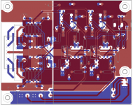
new try.
I would suggest exchanging the positions of each rectifier and its filter capacitor.
Then orient the capacitors so the grounded terminals are each just next to the stub
connecting to the analog ground plane. The stub is nearly cut off by a trace, so move
that trace out of the way to allow a wider connection. Here's an illustration of the stub
principle in a power amplifier: http://hifisonix.com/wordpress/wp-c.../How-to-wire-up-a-Power-Amplifier_Updated.pdf
Last edited:
aha.. i get that. never thought about direct coupling of the rectification smoothing caps to create the ground.. much better idea. using that method means that i dont technically need a ground plane in that area until between the caps which can be routed via traces to the main ground plane then use that to couple each input/output circuit ground.
food for thought 🙂
food for thought 🙂
i dont technically need a ground plane in that area until between the caps which can be routed
via traces to the main ground plane then use that to couple each input/output circuit ground.
Yes, just wide traces can go between the two caps, and the stub from the center to the analog plane.
The audio current goes through those caps to ground via the stub (because of the series voltage regulators).
Last edited:
thinking about it i can take traces off from the + - rectification smoothing caps to the regulation + - planes as well. i'm liking this idea much better than cutting the ground plane.
i also like the other idea of removing the input signal cold to a separate plane that way no input noise (most potential noisiest part of the audio circuit) can get in apart from signal hot.
i also like the other idea of removing the input signal cold to a separate plane that way no input noise (most potential noisiest part of the audio circuit) can get in apart from signal hot.
i also like the other idea of removing the input signal cold to a separate plane that way no input noise
(most potential noisiest part of the audio circuit) can get in apart from signal hot.
Do you really need those big input coupling capacitors? If so, they should be tied down to the board
with nylon wire ties, which would mean 2 holes on the board for each tie to pass through.
i personally dont need them as i'm using an RPi which as 0v output offset but its nice to have the function, i must get round to adding some through holes for smaller caps such as WIMA. the big caps will have a 19mm stick on tie base stuck to the board (just fits nicely) so i can use 'zip ties'. these tie bases have a U shape to the middle of them so it will cradle the cap, if i use 4 i can place two back to back in the middle, one on the bottom and one on top all zip tied together. if i really wanted i can have custom band punched out down the workshop (free access to a turret punch and brake press) (i used to be a blacksmith).
side note on those boutique caps, from experience i have found that depending on the make/type its a good way to 'tailor' the sound. for instance some will soften the vocals to reduce sibilance, its all a compromise though.
side note on those boutique caps, from experience i have found that depending on the make/type its a good way to 'tailor' the sound. for instance some will soften the vocals to reduce sibilance, its all a compromise though.
think i have it now, just a little tidying up to do.
What's the function of pin 3 in the AC input connector?
pin 3 is board to case GND/PE if needed which will require a bridge rectifier network to decouple. or leave out to 'float' the board. might be needed might not but its there just in case.
having a bit of a mare time with bypass capacitors for the power pins on the BUF634's.
they wont join when i move the components closer to the pins of the opamp, which they should as they are connected to the same power line e.g. V+. they are basically isolating which should no happen.
they wont join when i move the components closer to the pins of the opamp, which they should as they are connected to the same power line e.g. V+. they are basically isolating which should no happen.
pin 3 is board to case GND/PE if needed
Then I'd keep the power plane (with pin 3, the 2 rectifier grounds, and the 2 filter capacitor grounds)
separate from the audio plane, by making a vertical slit above the top rectifier, and also a vertical slit
below the bottom rectifier. Then connect the power and audio ground planes with a stub from the
junction of the filter capacitors, extending to the right.
Last edited:
you mean isolate the AC voltage rails/traces from the ground plane in case of eddy currents?
the only way i can separate the main gnd point is to box it off then use a resistor as a jumper as in how the input 0v plane is.
btw, thanks for all the help so far 🙂
the only way i can separate the main gnd point is to box it off then use a resistor as a jumper as in how the input 0v plane is.
btw, thanks for all the help so far 🙂
you mean isolate the AC voltage rails/traces from the ground plane in case of eddy currents?
Yes, or split that part of the plane off and connect with the stub to the audio plane.
You also could delete the power plane and only use traces, with that net connecting to the
audio plane with the stub off the center of the filter capacitors. Keep all that noisy stuff away
from the audio plane, connecting to it only at only one point.
ahhh wait i now see what your getting at, take a stub from the upper section of the T in the middle and route it through via the middle of the right rectifier and then isolate the pin 3 GND.
i did consider using nets instead of the power planes. might give that a go, would certainly reduce the possibility of stray currents. just easier to understand planes then nets.
i did consider using nets instead of the power planes. might give that a go, would certainly
reduce the possibility of stray currents. just easier to understand planes then nets.
Yes, either way would be ok, and both can isolate the noisy stuff from the quiet ground.
Sketches would be easier, but I have no way to do that right now.
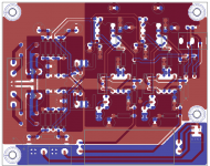
here is what i have done now. 'GNDA' top layer ground plain for REG/REC duties. i have let the REG caps naturally bridge on the GNDA plain but isolated the 'G' pin, this is bridged by a resistor to the main audio GND. isolated the noisy bits or the REG/REC area.
main GND and input 0v are connected to GNDA
the board now has three separate ground plains, GNDA for REG/REC duties, GND for main audio duties and 0v for audio IN duties.

main GND and input 0v are connected to GNDA
the board now has three separate ground plains, GNDA for REG/REC duties, GND for main audio duties and 0v for audio IN duties.

Last edited:
the board now has three separate ground plains, GNDA for REG/REC duties,
GND for main audio duties and 0v for audio IN duties.
It's better to disconnect the two filter capacitors' common leads from the audio ground plane,
and instead run their commons to one point together on the stub. Then extend the stub rightward
to the audio ground plane. This is because the center of the connection between the two
filter capacitors' commons has the least noise, so that's where the audio plane should connect.
ahh ok, so i have to use the leg of the T for audio ground duties. burger thats going to be awkward. i thought if i make the top of the T the whole plain then i could just connect anywhere. is this because of when the the voltages bounce from + to - they will try and go to the nearest cap pin instead of between them?
so i have to use the leg of the T for audio ground duties.
Think of the charging currents through the two filter capacitors, which consist of narrow pulses at 120Hz.
You don't want to couple these to the audio plane by conduction. So, you locate the lowest noise point
in the entire power circuit, and connect that one point to the audio ground plane with a short wide trace.
It has to be connected at only one point or there would be a ground loop, which would increase the noise.
The lowest noise point in the power circuit will be the center of the trace where the two filter capacitors'
commons join together. This is where, to a first order approximation, the two ripple currents cancel out,
leaving the least voltage noise. Then, when this low noise point is connected to the audio ground plane,
the least noise current will flow into it.
Last edited:
- Status
- Not open for further replies.
- Home
- Amplifiers
- Headphone Systems
- splitting ground planes
