The Yaoin Tube buffer...:
Arne K
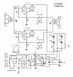
Hi, I have a board with 6j1 that has a circuit same as this but with different voltage and resister values.
The plate voltage is 83V.
The resistor 30K is 330K, 1k is 470R (Rb), 20k is 2K (Rk).
I am using a Russian 6j1p tube now and I wonder if the Rk value is too low.
I have tried to use the cathode follower calculator but I have no idea how to read the values from the datasheet I found here.
TIA if anybody can help me read those values.
file:///D:/_temp%20DNG/_audio/Tube/6Z1PEV%20english%20data.pdf
Hi ChuckT;
nobody can read a file on your hard drive. To get an idle current you may divide voltage drop on 30K on it's value. Then multiply it by 470 Ohm and get a voltage between G1 and cathode. Looking at the curves, check if it is the voltage needed for such a current.
nobody can read a file on your hard drive. To get an idle current you may divide voltage drop on 30K on it's value. Then multiply it by 470 Ohm and get a voltage between G1 and cathode. Looking at the curves, check if it is the voltage needed for such a current.
My apologies, I copy the wrong link to my computer.
Here is the correct one.
http://www.mif.pg.gda.pl/homepages/frank/sheets/112/6/6Z1PEV.pdf
Cathode (pin 2) voltage is 7.67V, G1 (pin 1) is 3.57V , so is 3.57v - 7.67v = -4.1V the bias voltage. Sorry, this buffer is my first real attempt for tubes.
Voltage drop between 330k is 0.83V
Here is the correct one.
http://www.mif.pg.gda.pl/homepages/frank/sheets/112/6/6Z1PEV.pdf
Cathode (pin 2) voltage is 7.67V, G1 (pin 1) is 3.57V , so is 3.57v - 7.67v = -4.1V the bias voltage. Sorry, this buffer is my first real attempt for tubes.
Voltage drop between 330k is 0.83V
Last edited:
My apologies, I copy the wrong link to my computer.
Here is the correct one.
http://www.mif.pg.gda.pl/homepages/frank/sheets/112/6/6Z1PEV.pdf
Cathode (pin 2) voltage is 7.67V, G1 (pin 1) is 3.57V , so is 3.57v - 7.67v = -4.1V the bias voltage. Sorry, this buffer is my first real attempt for tubes.
Voltage drop between 330k is 0.83V
Sorry, I think I am quite mixed up.
Pin 1 (G1) is -0.41V (another channel is -0.47v)
Rk (2k resistor) is 3.3V
Hi, some questions for modification.
I have a yaqin cd1 with original 12ax7, how much current originally flows in the tube?
in your opinion how much current is the transformer able to supply?
if I modified it with an ecc88..I would need more current.
I would like an ecc88 and more current.
Thanks
I have a yaqin cd1 with original 12ax7, how much current originally flows in the tube?
in your opinion how much current is the transformer able to supply?
if I modified it with an ecc88..I would need more current.
I would like an ecc88 and more current.
Thanks
50 to 100mA are more than enough for the anode voltage.ECC88 or 6DJ8 takes 6,3vac or dc on the filaments. 12AX7 takes 12,6. Be carefull. Why do you want to make that modification? It's a buffer I think!! 12AX7 is a very good tube.
Hello everyone,
I finally built the buffer following the schematic from post#1. Surprisingly, the output was only 750mV instead of 960 or 980 while the input voltage was 1Vp/p.
Is there any explanation for that result? I supplied the input with all available pulses, and there was no distortion, hum, or other anomalies. The only reason I can think of is the floating heaters 6,3VDC supply. if this is the problem, I will ground the negative output through a 100nF ceramic capacitor.
Your answers would be valuable to me.
Thanks a lot.
- Home
- Amplifiers
- Tubes / Valves
- Tube Buffer 6J1 / 5654 (6AK5)