If I were going to judge OTs, there is a list of measurements I would make.
Obvious things, like whether it does match the impedances spec'd, and that it handles the power claimed over the bandwidth claimed. For SE it needs to be able to handle the DC current and still have adequate primary inductance for the LF end.
There are subtle design issues in trading off leakage L versus distributed C that depend on the interleaving used. They are supposed to be arranged so that at resonance, the spec'd loading on the OT provides critical damping of the resonance peak. If not, then you either get peaking or exagerated roll-off of freq. response near the HF end. (depending on whether the reactances of the leak L and dist C are below or above the reflected load Z at resonance)
For P-P OTs, one should check the impedance and winding resistance balance between the two primary halves. Also check the leakage L and distributed C (or check BW) for each primary half. Most OTs will fail badly here. Proper design requires a split bobbin with symmetric windups on each section.
Then check the LF magnetizing current at full power voltage. Many OTs over state the LF response, with high magnetizing current occurring there. (particularly undersized ones) Really good ones will be a bit oversized.
UL taps or CFB windings should be tightly coupled to the secondary. (check leakage L ) (leakage L varies with turns squared, so one has to take that into account)
Check primary inductance versus AC (and DC for SE) signal level. Most common core materials loose significant permeability at low signal level. (this shows up also as magnetizing current that refuses to linearly drop off with V at low voltages, using a Variac to excite them ) Some OTs use exotic core materials to improve on this issue. Pin-striping with Mu metal lams is another fix. Another fix is to inject some small amount of HF "bias" into the amplifier to overcome OT core hysteresis or low permeability. (similar to what was used for magnetic tape recorders.) Toroid cores do better here too for holding up permeability, since the grain orientation is 100% in the correct direction (improving permeability and primary inductance). However, the toroid core is much more sensitive to DC imbalance. Some E-I cores are stacked with alternating groups of lams in the same orientation, to make small effective air gaps to handle some DC. That impacts primary inductance however. A low source impedance can fix the low level problem also.
There is also the dielectric insulation of the windings and layer insulations that may effect sound quality, similar to capacitor dielectrics. Vacuum impregnating the windings with epoxy or wax is used to improve the insulation strength and longevity (preventing loose turn vibration), but will also increase the dielectric effects (and distributed C). One could do some common mode (shorted primary to shorted secondary) dielectric tests with distortion sensitive test gear, much like used for testing caps.
I wouldn't worry about silver windings, a tiny effect, except on the wallet.
There are some special techniques like the Mac unity coupled (using bifilar winding sections), or Circlotron design, that can dramatically improve bandwidth. Circlotron just needs 1/2 the turns of usual. Low Z primary OTs are easier to get bandwidth due to fewer turns. This favors high current tubes that can handle that. Really high primary Z OTs for transmitting tubes are a disaster, and will require exotic expenditures (with multiple custom winding attempts) just to get them to work at all satisfactorily.
If the OT can pass all those tests well, then the sound quality is solely a feature of the circuit design.
For the very best and simplest approach to getting high OT performance without spending exotic amounts, one would use a Circlotron design with a low source Z drive. (rarely done) Most of the amplifiers around are copies of classic designs with little attention to OT optimisation except paying for an expensive one. Just try and get any of these data measurements from the OT manufacturers.
Although Plitron is pretty good on data, but the price ... ouch.
Last edited:
Is there anything to be said about ratio of inductance to primary impedance by turns ratio? I've noticed that some have their personal rule of thumb, like 10 Henries per 1K of nominal impedance, but some well regarded transformers with reportedly good or decent LF performance have significantly less.
10 Henries per 1K sounds like a SE OT requirement for 20 Hz low pass.
Xl = 2 * pi * f * L
2*pi*20*10 = 1256 Ohms, just over the 1K Z. That will still be making some phase shift there however with near equality between Xl and Z.
A P-P OT might have 40 Henries per 1K Z.
Xl = 2 * pi * f * L
2*pi*20*10 = 1256 Ohms, just over the 1K Z. That will still be making some phase shift there however with near equality between Xl and Z.
A P-P OT might have 40 Henries per 1K Z.
A deeper understanding will always help in designing and debugging circuits. You need to start from the basics, then work up from there. For example, you seemed to be unclear about the connection between inductance and bass response; if this is so then I suspect you have a long way to go.Hearinspace said:Thanks DF. I understand the power / distortion tradeoff to a degree. Not sure if you saw the top of the thread or not, but my question is more about the transformer than anything. The combination of its complexity and one fellow's approach to building the design around it one the one hand, and the ETF shootout comparison of 300B transformers on the other hand got me to wondering more about how to view / use the OT and whether I could get a deeper understanding of what's really doing what.
Is there anything to be said about ratio of inductance to primary impedance by turns ratio? I've noticed that some have their personal rule of thumb, like 10 Henries per 1K of nominal impedance, but some well regarded transformers with reportedly good or decent LF performance have significantly less.
hmmm.... define "nominal impedance" and we can start a discussion.
Otherwise:
DCR is also a factor to look at, as well if there is any HF ringing and how well the transients are handled, so you need to consider leakage inductance and capacitance... Then of course there is power handling and just basic mechanical considerations. It would seem enough to make you want to give up building your own! But that isn't all... the valve/tube is very important to consider in all calculations.
For example I take the Tango XE-20s which is a decent OPT but only has primary impedance of something like ~16 Henries on the 3.5k primary windings (into whatever correct load it is reflected into)
The -3dB low frequency cutoff point can be determined by the following formula:
f = Z/(2*Pi*L)
Z is the primary source impedance (reflected impedance in parallel with the source impedance presented by the tube's plate)
L is the primary inductance.
So lets take for example a 2a3 driving a Tango XE-20s on the 3.5K ohm taps. Lets run the 2a3 at 250V A-K biased at -45V on the grid giving an Rp of 800 ohm, just like in the RCA specs sheet.
Z= (3.5k +800)/2 = 2150 ohm
L= 16H
f= 2150/(2*Pi*16) = ~21 Hz
I think you will agree that this does not look bad! In fact it is pretty darn good.... And when you look at the Tango specs sheet, this pretty much lines up. There is even more to consider, because primary inductance can be measured at different frequencies, and of course your speaker is an inductive load, etc.... so even more factors that can be considered.
But after you do the maths and feel somewhat confident, its best to just build it and see how its sounds. 🙂
Ian
Last edited:
You calculated the parallel resistances in the wrong way. 800||3.5k is Z = (800 x 3500)/(800+3500) = 651. With 16H this gives a rolloff at 6.5Hz.soulmerchant said:So lets take for example a 2a3 driving a Tango XE-20s on the 3.5K ohm taps. Lets run the 2a3 at 250V A-K biased at -45V on the grid giving an Rp of 800 ohm, just like in the RCA specs sheet.
Z= (3.5k +800)/2 = 2150 ohm
L= 16H
f= 2150/(2*Pi*16) = ~21 Hz
Many thanks DF. I thought something was wrong with my calculation.... Proof again that checking your calculations a few times is always wise!
So to go further, I always was suspicious of the 16H value... If you look at the specs sheet, this value is not easy to interpret. Some people have claimed to have measured it, and it came somewhere closer to 10 for 3.5k
So for our exercise, let's imagine its only 10H.
That would give a 3db rolloff at a mere ~10.4 Hz which is very impressive.
anyway, the point I was trying to make was that this definition of "nominal impedance" is unclear.
If the original poster meant primary source impedance, then perhaps it would work. Still, I think you will agree that all the other factors such as I mentioned are also very important considerations.
Also - if you look at the frequency response curves from Tango, you will see that real measured and plotted values are not the same. The real world, it seems often fares a bit worse.
Ian
Last edited:
Using Crazy Drive in output stages
I am not worried about high output impedance because I am interested in building a transconductance amplifier, which should be also linear, preferably without much feedback. All that would be needed for current-driving a full range speaker. Is Crazy Drive useful also with output pentodes and beam tetrodes, such as 6L6 or EL34 ?
And then there is a new kid on the block, that changes the whole game: Crazy Drive, which is a modification of grid 2 drive. (requires higher drive V versus traditional grid 1 drive. Typically 3X for TV Sweep tubes.)
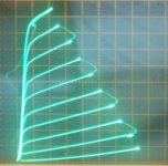
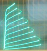
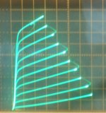
It gives pentode tubes near-linear plate curves, that don't much care how you plot the load line across them. Revolutionary is an understatement. Nothing on the Planet comes close. It mainly is useful with TV Sweep tubes (that have low V grid 2), which are conveniently cheap for some low demand (non CB radio) types, but limited in quantity for commercial purposes. (DIY useful only essentially) See the curves below for a 26LX6. They still need some form of N Fdbk to lower their output or source Z however for OT performance and speaker damping factor. (Their native Zout looks like a pentode Zout)
I am not worried about high output impedance because I am interested in building a transconductance amplifier, which should be also linear, preferably without much feedback. All that would be needed for current-driving a full range speaker. Is Crazy Drive useful also with output pentodes and beam tetrodes, such as 6L6 or EL34 ?
Crazy Drive has been tried with a 6L6WXT tube and it worked. But it was somewhat "strained" to get the tuning to work. It wanted to develop a gain "bulge" in the middle of the plate curves (versus current), which I had not seen before with any of the low screen V TV tubes. So I'm not sure what to expect with other high screen V "audio" type tubes. (I don't have any others to test here. This is cheap TV Sweep tube territory around here.) The "audio" tubes are not as attractive for g2 drive or Crazy Drive (a variant of g2 drive) due to the high g2 drive voltage required. The LV TV Sweeps are a better fit.
But the 6L6WXT did maintain a fairly constant Rp versus current.
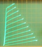
Looking at the 6LB6 in Crazy Drive below (a typical LV screen V TV Sweep tube), you will notice the Rp is decreasing at higher currents. (more sloped lines) This can be remedied by somewhat different tuning of the Crazy Drive resistors. By sacrificing some gm, the top curves can be brought down to similar Rp as the lower current curves (but will require more drive voltage to reach the full range of plate current then). So there is some range of optimization possible.
Another option for a transconductance stage is to use a current sampling resistor under the cathode of the output tube, with feedback to the driver stage. This can make output current proportional to drive signal. And it could be used with either audio tubes or TV tubes, in either pentode or Crazy mode.
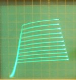
1) 6L6WXT in Crazy Drive (the C tracer 70V step range limited the range of plate current shown in a single graph with the 6L6WXT)
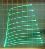
2) 6l6WXT in grid 1 drive
3) 6LB6 in Crazy Drive (optimised for gain)
But the 6L6WXT did maintain a fairly constant Rp versus current.
Looking at the 6LB6 in Crazy Drive below (a typical LV screen V TV Sweep tube), you will notice the Rp is decreasing at higher currents. (more sloped lines) This can be remedied by somewhat different tuning of the Crazy Drive resistors. By sacrificing some gm, the top curves can be brought down to similar Rp as the lower current curves (but will require more drive voltage to reach the full range of plate current then). So there is some range of optimization possible.
Another option for a transconductance stage is to use a current sampling resistor under the cathode of the output tube, with feedback to the driver stage. This can make output current proportional to drive signal. And it could be used with either audio tubes or TV tubes, in either pentode or Crazy mode.
1) 6L6WXT in Crazy Drive (the C tracer 70V step range limited the range of plate current shown in a single graph with the 6L6WXT)
2) 6l6WXT in grid 1 drive
3) 6LB6 in Crazy Drive (optimised for gain)
Attachments
Last edited:
Well, I went to set up some tubes in Crazy Drvie mode for pics with a more constant Rp, and looks like I will have to eat my words on that. The Rp seems to simply depend on plate current, higher current producing lower Rp (steeper slope).
Appears I was mis-lead previously by the limited plate current step range with Rg21 increased (Rg21 being the resistor from grid 2 to grid 1, causing less g1 drive, and reduced sensitivity).
Anyway, here are the pics I took for 6LB6 and 26LX6.
50mA/div Vert., 50V/div Horiz.
Low Rg21 is like 1K, and high Rg21 is like 2.75K
1) 6LB6 low Rg21 (high gain)
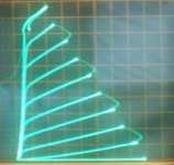
2) 6LB6 high Rg21 (low gain and increased step V range to compensate)
3) 26LX6 high Rg21 (low gain and increased step V range to compensate)
4) 26LX6 high Rg21 (low gain and reduced, or same, step V range, ie. no compensate)
As you can see from the last two pics, these are actually the same Crazy Drive Rg21 setup, but just different step V range to get lower or higher plate current range. Looks (deceivingly) like the pic 4) (with reduced step range) has more constant Rp than pic 3) with increased step range. {but for the SAME plate current levels, I think the Rp is the same}
Well, now it DOES look like there is SOME effect on the Rp for higher plate current between low gain and high gain setups. pic 1) versus pic 2)
But not as much as I was hoping for.
One funny effect of Crazy Drive, is that most of the TV tube types look the same as each other after getting tuned up. No more kinks, same kind of plate curves.
Appears I was mis-lead previously by the limited plate current step range with Rg21 increased (Rg21 being the resistor from grid 2 to grid 1, causing less g1 drive, and reduced sensitivity).
Anyway, here are the pics I took for 6LB6 and 26LX6.
50mA/div Vert., 50V/div Horiz.
Low Rg21 is like 1K, and high Rg21 is like 2.75K
1) 6LB6 low Rg21 (high gain)
2) 6LB6 high Rg21 (low gain and increased step V range to compensate)
3) 26LX6 high Rg21 (low gain and increased step V range to compensate)
4) 26LX6 high Rg21 (low gain and reduced, or same, step V range, ie. no compensate)
As you can see from the last two pics, these are actually the same Crazy Drive Rg21 setup, but just different step V range to get lower or higher plate current range. Looks (deceivingly) like the pic 4) (with reduced step range) has more constant Rp than pic 3) with increased step range. {but for the SAME plate current levels, I think the Rp is the same}
Well, now it DOES look like there is SOME effect on the Rp for higher plate current between low gain and high gain setups. pic 1) versus pic 2)
But not as much as I was hoping for.
One funny effect of Crazy Drive, is that most of the TV tube types look the same as each other after getting tuned up. No more kinks, same kind of plate curves.
Attachments
Last edited:
Absolutely. Any of the normal voltage derived Neg. feedbacks will do that. Global or local.
Current derived Fdbk for high Rp mentioned above is the unusual case.
Crazy Drive provides about 1/3 the tube gain of g1 drive however, so is at some disadvantage to get low output Z. (for a Schade like single stage loop.) Taking the feedback back to the driver cathode can increase that loop gain by another 20X or 50X easily, so the low Rp problem is readily solved. Global N Fdbk will lower the output Z further.
Last edited:
hmmm.... define "nominal impedance" and we can start a discussion.
Nominal impedance is the named impedance . . . . . . and in the end it's the number on the label.
Hi DF,A deeper understanding will always help in designing and debugging circuits. You need to start from the basics, then work up from there. For example, you seemed to be unclear about the connection between inductance and bass response; if this is so then I suspect you have a long way to go.
You're right that I have plenty to learn, but I am dimly aware that the way you drive the transformer can change things (an example) and I'm interested in learning more about that. Smoking-Amp's post puts much of the information into a package that isn't too hard to grok and makes for a base on which to learn more. Thanks!
Absolutely. Any of the normal voltage derived Neg. feedbacks will do that. Global or local.
Current derived Fdbk for high Rp mentioned above is the unusual case.
Crazy Drive provides about 1/3 the tube gain of g1 drive however, so is at some disadvantage to get low output Z. (for a Schade like single stage loop.) Taking the feedback back to the driver cathode can increase that loop gain by another 20X or 50X easily, so the low Rp problem is readily solved. Global N Fdbk will lower the output Z further.
I notice that in the several times I've seen you refer to Rp you use a capital. Some texts use it for AC and others for DC and some for both. Which are you referring to?
That would be AC. I guess I should be using rp. Some might not catch the meaning though of an effective resistance.
By "effective" I've taken the meaning that it only appears to be so as a result of looking at its function within the behavior of the overall circuit. IOW effective rp is not independent of the entire circuit. Have I got it right?
Yes, although I'm not sure I'm using it correctly according to the usual textbooks. They might leave rp as just the tube component, and then Zout as the effective AC impedance (after feedback effects). Certainly nothing like a real resistor there. In the practical sense, we are concerned with what the speaker sees transformed through the OT for the source impedance.
Maybe someone can set the convention straight here?
Maybe someone can set the convention straight here?
To bring it down to earth a little more - If we were to ask a transformer manufacturer to wind a custom transformer for a circuit with Local Plate to grid feedback (Schade) and he says, "Sure, and what's the rp of the output tube?" , would we give him the book value for the tube at that operating point or the calculated/measured effective value for the tube in that circuit?
A transformer winder doesn't really need your source impedance; it varies with signal, etc. and doesn't effect the transformer maker's choices. Reflected load, expected DC offset, peak magnetization, minimum acceptable primary inductance at idle, and maximum acceptable leakage inductance are things that *do* need to be decided.
All good fortune,
Chris
All good fortune,
Chris
Well, source rp is not really how one would spec an OT (with the possible exception of a triode in SE). Although rp often gives a ballpark estimate. The OT primary Z is fitted to the tube plate curves for optimum power transfer (via a load line).
There is usually considerable leeway in how that might be done however, since the tube specs typically allow higher V or higher I operation, as long as this still meets the power Pdiss limits. (the slope of the load line just has to stay within the Pdiss hyperbola, and obey the max V and max I tube limits) One might be swayed one way or the other on primary Z by distortion obtainable, output damping factor, or B+ that is available. Optimum Vg2 (for pentode mode) is determined by the slope as well. For a P-P amp, the load slope might be chosen to minimise the 3rd harmonic for example, since the 2nd harmonic gets cancelled by the P-P. But that depends in detail on the plate curves.
One does not alter the OT primary Z usually when the N Fdbk is changed, for example, even though that changes the output Z.
For a SE triode there are some rules of thumb for primary Z, like 3X rp for best power, and 5X rp for low distortion. Anything else, and one consults the plate curves for best fit, or the recommendations on the datasheet. But that's only because SET designers are allergic to external feedback. They are stuck in a narrow groove for handling triode distortion.
Last edited:
A transformer winder doesn't really need your source impedance; it varies with signal, etc. and doesn't effect the transformer maker's choices. Reflected load, expected DC offset, peak magnetization, minimum acceptable primary inductance at idle, and maximum acceptable leakage inductance are things that *do* need to be decided.
All good fortune,
Chris
I don't doubt what you say at all, but my question has formed over time around a lot of little things, one of which is an exchange I had last year with Monolith. I asked about their request for output tube rp on custom transformer orders and was told "it influences the design to a large extent". I wanted to understand how (especially as I wanted to look at ways to improve the amp mentioned below).
Well, source rp is not really how one would spec an OT (with the possible exception of a triode in SE). Although rp often gives a ballpark estimate. The OT primary Z is fitted to the tube plate curves for optimum power transfer (via a load line).
There is usually considerable leeway in how that might be done however, since the tube specs typically allow higher V or higher I operation, as long as this still meets the power Pdiss limits. (the slope of the load line just has to stay within the Pdiss hyperbola, and obey the max V and max I tube limits) One might be swayed one way or the other on primary Z by distortion obtainable, output damping factor, or B+ that is available. Optimum Vg2 (for pentode mode) is determined by the slope as well. For a P-P amp, the load slope might be chosen to minimise the 3rd harmonic for example, since the 2nd harmonic gets cancelled by the P-P. But that depends in detail on the plate curves.
One does not alter the OT primary Z usually when the N Fdbk is changed, for example, even though that changes the output Z.
For a SE triode there are some rules of thumb for primary Z, like 3X rp for best power, and 5X rp for low distortion. Anything else, and one consults the plate curves for best fit, or the recommendations on the datasheet. But that's only because SET designers are allergic to external feedback. They are stuck in a narrow groove for handling triode distortion.
You're absolutely right! SE. I don't have any political bias against P-P but of the amps I've built so far I've had the best luck with the single ended ones and as there's more experience there, when I'm asking about the output transformer that's what I usually have in mind.
I built Michael Koster's direct coupled, pentode driven, M2 circuit using a 35T as the output tube. The data sheet Rp for the 35T works out to something like 14000 Ohms (Eb=2000VDC, Ib=100mA). At the M2's much lower voltage of 500Vp-k @ 100mA it might be something like , I dunno, 4k - 8k? But with 100% Schade feedback the "effective" rp works out to something like 500 Ohms . . . . . but does the output transformer really "see" it as a 500 Ohm source impedance?
We've seen higher up the thread that a lower driving impedance can have positive effects on transformer performance. (I think this relates to your mentioned "5X rp for low distortion".) So, if somebody was to order from a winder who factors source impedance into the design (like Monolith) would they want the Schaded effective figure or the data sheet Rp adjusted for the operating point of the tube itself ? Is this a stupid question?
- Home
- Amplifiers
- Tubes / Valves
- Design based on the Output Transformer