Back around 2000 or so , looking for info on doing your own amp design, I ran across a web-page where the writer offered his view on the process. He said that as the output transformer was easily the most complex single component of the audio circuit it made sense to start with the OT, measure its characteristics and then work out the best circuit for driving it. At the time I knew nothing, had no test equipment or ability and in the usual newbe's race against time to arrive at the perfect sound , fog suddenly came over the horizon at the prospect of studying transformers.
Thinking about it now though it seems a reasonable approach and so my question is, if one wanted to go that route, what are the characteristics you'd want to test for, how would you test for them, and what are some of the ways you might then treat the results when designing the rest of the circuit?
I realize that the approach most of us have now is to choose a tube - often one that others have tried and found to sound good in their circuits - and then pick an OT with the appropriate (or often usual) impedance - this leaves us in the position of judging the quality of the transformer by how good it sounds in the circuit - but I wonder how much the perceived quality really has more to do with how suitable the circuit is for driving that particular transformer.
Anyhow, I think it would be an interesting way to go about a design, and my guess is that a lot could be learned from going that route instead of the usual 'tube as first step'.
I guess you first decide what you want/need, then choose what to build, and only then worry about parts needed.
SE versus P-P (higher power) make for some significant transformer differences.
(particularly DC current capability and LF bandwidth for SE)
But for any configuration, a low source impedance from the output tubes makes for better OT performance (an important effect), improves distortion, BW and speaker damping factor too. That low source impedance could be via triode output or a "local" feedback around a pentode, or CFB.
HF bandwidth is important if you are going to use a global (around the OT) N Fdbk. Then there is max Watt handling ability and DC handling ability, always good to oversize a little to avoid core saturation, especially for SE.
Then there is accuracy versus sound coloration. Getting the "right color" can cost you.
I guess you first decide what you want/need, then choose what to build, and only then worry about parts needed.
Hi,
Ok,maybe, but let's say we already have a pair of transformers on the shelf and we want to know what to do with them. I know that most of us will opt to start with a tube known to use that impedance of transformer, even some creative lights on this forum appear (to me , anyway) to be inclined to that approach , but I also know from reading posts here that while the traditionally cited primary impedance load for a 300B is 3K, ( ok , let's say 3k to 4K), some people here end up liking the sound you get with a 5K load better. So while it's convenient to think in handy pairings, (300B needs 3K, 2a3 needs 2K5 etc) there are other possible approaches in which the traditional or usual matches may not apply.
The European Triode Festival did a 300B transformer shootout using a single circuit to judge an array of transformer entries. There were winners and non-winners . I wonder if you can really say anything absolute about which one is better or worse based on which one sounded the best in that particular jig. Surely optimization has something to do with it where even if the primary Z is the same, the leakage L, stray C, winding DCR, Lprimary etc are all different. No?
So for the sake of convenience let me rephrase the question: Let's say we have a pair of transformers on the shelf rated to handle the power needed for the job. > What sort of tests could we do to know what kind of animal they actually are (beyond the simple spec'd primary impedance resulting from turns ratio) and then how would we use the acquired data to create a well matched circuit?
You can measure the DC resistance of the windings, lower is better. Determines OT loss and damping factor effect. You can measure the leakage L of the OT with an L meter. (Just put the L meter across the primary and short the secondary that is going to be used.) Check both sides of a P-P primary to secondary leakage L. (balanced is best, but rare) You can measure the bandwidth of the OT using a signal generator and a dummy resistive load on the secondary. (scope or DVM to measure output level versus frequency, assuming constant input level from generator, can check that too.) (good to find the OT resonance too, from this you can calculate the distributed C using the measured leakage L) Then you can check the OT LF power capability by measuring magnetizing current versus input level. (Variac to LV xfmr to secondary. Then a small resistor in series or a scope current probe to monitor peaking of the current)
SE versus P-P (higher power) make for some significant transformer differences.
(particularly DC current capability and LF bandwidth for SE)
But for any configuration, a low source impedance from the output tubes makes for better OT performance (an important effect), improves distortion, BW and speaker damping factor too. That low source impedance could be via triode output or a "local" feedback around a pentode, or CFB.
HF bandwidth is important if you are going to use a global (around the OT) N Fdbk. Then there is max Watt handling ability and DC handling ability, always good to oversize a little to avoid core saturation, especially for SE.
Then there is accuracy versus sound coloration. Getting the "right color" can cost you.
Ah, you posted while I was writing the above, so you've started to answer my question.
From your answer:
For low source impedance, that would be the ratio of tube rp to load impedance? Putting aside the question of power out (for the moment anyway) what is the optimum range as far as distortion is concerned? In my limited experience once the load z goes above a certain level the sound starts to sound thin, or dry. Is there a known limit?
HF bandwidth is related to winding capacitance?
Leaving margin for power, avoiding saturation, perhaps I understand (to a limited degree). (Big is good but in balance with an eye on rising capacitance?)
You can measure the DC resistance of the windings, lower is better. Determines OT loss and damping factor effect. You can measure the leakage L of the OT with an L meter. (Just put the L meter across the primary and short the secondary that is going to be used.) Check both sides of a P-P primary to secondary leakage L. (balanced is best, but rare) You can measure the bandwidth of the OT using a signal generator and a dummy resistive load on the secondary. (scope or DVM to measure output level versus frequency, assuming constant input level from generator, can check that too.) (good to find the OT resonance too, from this you can calculate the distributed C using the measured leakage L) Then you can check the OT LF power capability by measuring magnetizing current versus input level. (Variac to LV xfmr to secondary. Then a small resistor in series or a scope current probe to monitor peaking of the current)
Thanks Don,
So then how to look treat those characteristics. If I already have the transformer in hand, Can I do things to compensate for or make best use of the Leakage L and distributed C?
Is the only answer to magnetizing current to stay below a certain drive level?
HF bandwidth is related to distributed capacitance and leakage inductance. Together they form a resonance at HF, beyond which the OT generally performs like Cr_p. Distributed C draws drive current at HF, which a low source tube impedance can overcome. Leakage L disconnects the primary from the secondary at HF, causing the BW to collapse. It could be overcome with a current source drive (hi Z source), but that is not normally done.
The combination of the leakage L and distributed C also causes what is called a two pole phase response at HF, approaching the resonance freq. This makes the phase change too fast for the enclosed loop gain to drop off in time to prevent a power oscillator forming from a global feedback loop. Not so big a concern without global feedback, except for HF end roll-off. Low source impedance can overcome the distributed C and change the response to a single pole roll-off for the global Fdbk loop. (so no power oscillator) HF will still roll-off (more slowly) due to the leakage L.
Selecting the best primary Z is important for determing power output for a given B+ voltage. Higher Z will mean higher B+. For triodes, there is also less distortion from the triode with a higher primary Z. So there is a trade-off between optimum power and low distortion.
Pentodes on the other hand have an optimum Z window. Low primary Z leads to 3/2 (tube) power distortion (like for triodes), (a more vertical load line, and lower B+), while high primary Z leads to screen grid current distortion. (higher B+, lighter loading on the pentode allows the plate V to drop below the screen V more often, which increases screen current, causing distortion)
Magnetising current increases at LF and with higher signal level (consuming tube current and increasing distortion). This sets a LF limit for the OT for a given Wattage. Less Watts, then you can go lower in freq. SE OTs are especially sensitive to this limit, since the DC tube current eats up half the magnetising ability of the core. A bigger OT can give you more head room here, but increases distributed winding capacitance. Low output source Z can simply overcome the magnetising current easily for reduced distortion. However, magnetising current increases very rapidly at the LF end, so the OT LF response can only be moderately extended that way (low Z source).
There is also an issue with transformer core material having less permeability (ability to function per current drive) with small signals. That makes the magnetizing current disproportionately large (it's still relatively small actually) for low level signals. So the tube distortion tends to increase with low level signals due to the extra current. Can either go to exotic expensive core materials, or once again, low source Z can overcome that.
By now it should be obvious that low source Z fixes most (but not all) OT problems. Low source Z is most easily obtained with low Rp triodes, big tubes, and next up, is using a "local" feedback loop which does not include the OT in the loop. Global N Fdbk also reduces the source Z, but only so much can be applied if the OT is limiting the HF bandwith to begin with. While the "local" Fdbk solution can allow high amounts of N Fdbk for fixing poor or so-so economical OTs. Traditional high global Fdbk only amplifiers, like the Williamson, require high quality OTs.
Last edited:

And then there is a new kid on the block, that changes the whole game: Crazy Drive, which is a modification of grid 2 drive. (requires higher drive V versus traditional grid 1 drive. Typically 3X for TV Sweep tubes.)
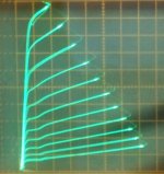
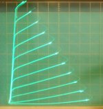
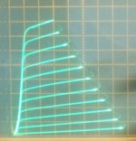
It gives pentode tubes near-linear plate curves, that don't much care how you plot the load line across them. Revolutionary is an understatement. Nothing on the Planet comes close. It mainly is useful with TV Sweep tubes (that have low V grid 2), which are conveniently cheap for some low demand (non CB radio) types, but limited in quantity for commercial purposes. (DIY useful only essentially) See the curves below for a 26LX6. They still need some form of N Fdbk to lower their output or source Z however for OT performance and speaker damping factor. (Their native Zout looks like a pentode Zout)
1) traditional grid 1 drive
2) Crazy Drive
Attachments
Last edited:
"For low source impedance, that would be the ratio of tube rp to load impedance? Putting aside the question of power out (for the moment anyway) what is the optimum range as far as distortion is concerned? In my limited experience once the load z goes above a certain level the sound starts to sound thin, or dry. Is there a known limit?"
I assume this is referring to a SET case. (or possibly triode P-P) With a high enough load Z, the tube is at least going to be very linear, not sounding like a typical SE amp (reduced 2nd harmonic). High load Z would also make for high distributed capacitance in the OT, (more turns), so this may limit the HF portion of the signal. Could be other effects too, dunno. Maybe someone can chime in on this.
I assume this is referring to a SET case. (or possibly triode P-P) With a high enough load Z, the tube is at least going to be very linear, not sounding like a typical SE amp (reduced 2nd harmonic). High load Z would also make for high distributed capacitance in the OT, (more turns), so this may limit the HF portion of the signal. Could be other effects too, dunno. Maybe someone can chime in on this.
Last edited:
Anyhow, I think it would be an interesting way to go about a design, and my guess is that a lot could be learned from going that route instead of the usual 'tube as first step'.
I far prefer the approach you see in SY's designs (he's not alone, but his documentation is better).
Start with a clear set of performance objectives. Design backward through the amp from output to input with constant reference back to the design objectives.
Design to ensure that the drive requirements of each stage are exceeded by the preceding stage.
I think Miles Prower also did some design process documentation around this with one of his amps - le Renard perhaps?
Hi,
I don't see any disagreement with your statement. I'm simply asking:
If I start with a pair of transformers I already have, with required secondary impedance and built to handle the power out needed by the speaker load, how do I make useful measurements of the transformer and then translate the resulting data into a design best suited to driving that particular transformer (ie. not solely based on the Primary impedance printed on the label)?
To put it a different way, I'm not very good at theory and don't know enough to program in all the characteristics of parts in LTspice so everything I learn (which I admit isn't much) comes from putting something together and putting a meter on it. If I want to learn about output transformers then this is the kind of question I have to ask.
Thanks
I think you meant to say, "not exceeded" in your 3rd sentence, but I otherwise agree.I far prefer the approach you see in SY's designs (he's not alone, but his documentation is better).
Start with a clear set of performance objectives. Design backward through the amp from output to input with constant reference back to the design objectives.
Design to ensure that the drive requirements of each stage are exceeded by the preceding stage.
I think Miles Prower also did some design process documentation around this with one of his amps - le Renard perhaps?
It seems to me that any load by any transformer in a push-pull output circuit will cause some real-time dynamic range compression, so one question might be how much of that do you want? In a guitar amp I like having a significant amount of that because it gives the guitar more sustain. In a Hi-Fi amp, I would still want some personally, so program material would be less irksome and thereby easier to listen to. If you want maximum "bang", I guess you'd want minimal compression. In a single ended output stage, the heavier load would increase even harmonic and I.M. distortion products, rather than compression as it's usually defined.
I've been told that a "rule of thumb" is to load the output tube(s) at about 4 times their output Z for Hi-Fi. I haven't done the measurements, but I wonder if that's enough to call it Hi-Fi (?). But if you unload the tubes more by jacking up the transformer primary Z, then the transformer will reduce the output voltage (bigger pri/sec windings ratio), and therefore watts. Volts being a squared term in the power formula means power would go down fast.
To measure frequency response of a transformer, I would load the secondary with a resistor (8ohm?), and drive the primary from a low Z generator, with a variable resistor in series feeding the tranny that was about what the tube(s) Z would be. You can do this test at relatively low power levels. I'd look not just for roll-off at both ends of the spectrum, but also visable distortion of a sinewave on a scope (especially at the low frequency end). My 40 watt Hammond trannies got pretty distorted at 20HZ and below. I'm only pushing them to 30watts rms max. My "expert" friend says the low end distortion is about core size. The rolloff on the high end will have everything to do with how you establish your phase margin if there is any negative feedback that includes the tranny. If you don't understand what phase margin is, you may end up with a blown speaker.
To measure the output Z of the output tubes feeding the tranny, I'd replace the tranny with a variable high wattage maybe 10K resistor, and with a sinewave applied I'd crank the variable resistor until the voltage across it is the same as the voltage across the tube(s), then remove the variable R from the circuit and measure it. The interesting thing here is that you'll probably get a different reading at low levels vs high levels, since at low levels, both output tubes are biased on (assuming a class AB circuit) , and past a certain signal voltage level, one of the tubes in a push-pull will have turned off completely for much of the duration of a half cycle, so from the point of view of the output tranny, the source Z becomes approximately half of what it was near zero volts, when both output tubes are conducting...
Indeed, my earlier comment about measuring the freq. response of the OT should have included a source resistance in series with the (probably low Zout) signal generator to model the nominal output tube Rp.
----
"I'd replace the tranny with a variable high wattage maybe 10K resistor, and with a sinewave applied I'd crank the variable resistor until the voltage across it is the same as the voltage across the tube(s), then remove the variable R from the circuit and measure it."
Assuming that's AC voltage, they should always be the same, right? (being connected together) I'm no expert on this measurement, but seems like one would want to find the point where the variable R load has the same AC as half the AC with a very light (high R) load. This may cause problems with the DC operating point though, unless the OT is left connected.
Last edited:
Any loading is a compromise between issues like power output and distortion. A good valve data sheet may show a plot, so you can choose whether you prefer volume or distortion - these are matters of personal taste.Hearinspace said:So while it's convenient to think in handy pairings, (300B needs 3K, 2a3 needs 2K5 etc) there are other possible approaches in which the traditional or usual matches may not apply.
Thanks DF. I understand the power / distortion tradeoff to a degree. Not sure if you saw the top of the thread or not, but my question is more about the transformer than anything. The combination of its complexity and one fellow's approach to building the design around it one the one hand, and the ETF shootout comparison of 300B transformers on the other hand got me to wondering more about how to view / use the OT and whether I could get a deeper understanding of what's really doing what.
Good point about the DC operating point getting shifted by the variable pot load. I'd put a coupling cap in there, off the plate feeding the VR. Perhaps a 1uF 600V cap (?) You could use an electrolytic for this too, but too high a value might temporarily shift the DC when the VR is rotated."I'd replace the tranny with a variable high wattage maybe 10K resistor, and with a sinewave applied I'd crank the variable resistor until the voltage across it is the same as the voltage across the tube(s), then remove the variable R from the circuit and measure it."
Assuming that's AC voltage, they should always be the same, right? (being connected together) I'm no expert on this measurement, but seems like one would want to find the point where the variable R load has the same AC as half the AC with a very light (high R) load. This may cause problems with the DC operating point though, unless the OT is left connected.
Since the tube circuit and the VR are in series for AC, when they each have the same amount of AC sinewave (at 1kHZ for example) voltage across them, they would have to be the same resistance as each other.
I'd also check this at several frequencies (20HZ, 100HZ, 10kHZ 20kHZ), part to make sure the coupling cap was an effective short for AC at the frequency I'm looking at, and part to see if there are any other FR anomolies (which there shouldn't be, unless the coupling cap is too small for 20HZ).
It would be difficult to do a fully legitimate "shootout" with OT's, because any shift in level (even 1/4 dB) may well sway one's opinion. Different transformers might have slightly different efficiencies. There's even a chance that the extremes of FR would be a little different with a given set of surrounding circuit impedances. I know a "tube guru" who did such a shootout with many different transformers covering a vast price range, and claimed he heard differences, but his buddy said he was there and couldn't hear any difference at all... His buddy is a non-technical person (perhaps more objective?) who's hearing may or may not be reference quality. Personally, I've had no regrets with Hammond transformers, so I figure why pay more? Many things are technically better, but not audibly better. Other weak links in the system can dominate by quite a lot.Thanks DF. I understand the power / distortion tradeoff to a degree. Not sure if you saw the top of the thread or not, but my question is more about the transformer than anything. The combination of its complexity and one fellow's approach to building the design around it one the one hand, and the ETF shootout comparison of 300B transformers on the other hand got me to wondering more about how to view / use the OT and whether I could get a deeper understanding of what's really doing what.
And then there is a new kid on the block, that changes the whole game: Crazy Drive, which is a modification of grid 2 drive. (requires higher drive V versus traditional grid 1 drive. Typically 3X for TV Sweep tubes.)
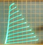
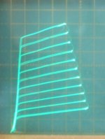
It gives pentode tubes near-linear plate curves, that don't much care how you plot the load line across them. Revolutionary is an understatement. Nothing on the Planet comes close. It mainly is useful with TV Sweep tubes (that have low V grid 2), which are conveniently cheap for some low demand (non CB radio) types, but limited in quantity for commercial purposes. (DIY useful only essentially) See the curves below for a 26LX6. They still need some form of N Fdbk to lower their output or source Z however for OT performance and speaker damping factor. (Their native Zout looks like a pentode Zout)
1) traditional grid 1 drive
2) Crazy Drive
That sounds intriguing! Is there a tread here about this 'crazy drive'? Search doesn't turn up anything.
Jan
Crazy Drive starts here:
http://www.diyaudio.com/forums/tube...nificent-television-tubes-47.html#post4574362
It starts out a bit discombobulated, since the early posts were extracted from another thread. Essentially an accidental discovery (on the curve tracer) that an earlier use of the technique works way better than anyone had seemed to ever notice. It does depend on tuning some resistors, which is easy to do when you can see the results on a curve tracer. The results of proper tuning are nothing short of spectacular. Seems to work well for most any TV Sweep tube. Even the $1 and $4 ones! Best tubes in the world for $1. (Well they were once on sale at that price a few years ago. $4 ones still avail.) There is no N Fdbk involved in this scheme either. But some N Fdbk will typically be needed to lower the output Z, which looks like a pentode in native mode. With the N Fdbk added, linearity should be spectacular.
Attachments

Last edited:
It would be difficult to do a fully legitimate "shootout" with OT's, because any shift in level (even 1/4 dB) may well sway one's opinion. Different transformers might have slightly different efficiencies. There's even a chance that the extremes of FR would be a little different with a given set of surrounding circuit impedances. I know a "tube guru" who did such a shootout with many different transformers covering a vast price range, and claimed he heard differences, but his buddy said he was there and couldn't hear any difference at all... His buddy is a non-technical person (perhaps more objective?) who's hearing may or may not be reference quality. Personally, I've had no regrets with Hammond transformers, so I figure why pay more? Many things are technically better, but not audibly better. Other weak links in the system can dominate by quite a lot.
When I look at the shootout entry requirements it seems the range of possibility is so broad that very different transformers can be set against each other. With the amplifier circuit set-up as a given it seems to me it would be a good way to test transformer winders' ability to design a transformer specifically for that circuit at those operating points. . . . . . but most of the transformers were off the shelf models and I don't know how their design considerations relate to the conditions of the test circuit.
I should add that I'm not criticizing their approach. It was likely a lot of fun and I for one would probably have enjoyed being there , but I'm now questioning the conclusion that I once had a tendency to draw, that the winners there are necessarily better than any of the other transformers without any relationship to the circuits they are in.
- Home
- Amplifiers
- Tubes / Valves
- Design based on the Output Transformer