Well, the 1st order of concern is always whether the tube can drive the load impedance presented by the OT, so power coupling is priority. That leaves some usable range however. I would imagine that Monolith wants the Schaded (or whatever "local" N Fdbk) effective source Z, but I would just send them both that and the tube rp (and the tube type too) to be safe. Clearly these people know something about what they are doing if they are asking for that info. They might also just be looking at how far they can go toward the low primary Z side of the available coupling window. Lower primary Z will make for a better performing OT. Usually there is a conflict between the designer wanting hi Z and the winder wanting a low Z primary.
The source rp and load together (||) determine the damping on the OT resonance. For the price they apparently charge, I guess they better know. (I would guess that a lot of traditional OTs around were not so fussy, and they only fixed the leakage L to distributed C balance for critical resonance damping if it was way off and ringing. It IS above the audible range. Leakage L is difficult to control tightly too. Wire tension. )
One thing that does work well for controlling (and minimizing) leakage L is using a long E lamination. (the 3 horiz. sections of the E are long) Some old high quality OTs were made this way. A long thin winding stack arrangement has low leakage L, toroids naturally take advantage of this, being stretched out around the toroid. Also the long E has more of the magnetic grain aligned in the right direction. There is even a technique that uses a double thick back to the E, with no I lams, which avoids butt joints in the lam stack. Giving near toroid features to the long E type design.
But if you are going to build some experimental amp initially, I think I would go with something cheap 1st, until you are sure about the amplifier performance. You may want to make changes. A low source Z can make even a cheap OT work quite well.
And for a SET type design, getting the 2nd Harmonic level set "right" is important for the "sound". This can determine the optimum primary Z for a particular tube. No 2nd harmonic (too high primary Z), and it may sound like a SS amp. That's why I prefer a P-P amp, where the 2nd H can be adjusted easily to taste, and can be adjustable for different music. Some would also say that setting a HF cutoff for SET is important too, usually the SET OT does this automatically. The limited LF end with SET, and weak speaker damping, are not sought out however. No "slam".
Last edited:
Again, really helpful - even the detail about conflicting ideals of designer and winder gives perspective.
Though the Monolith idea is off the table, your point about not spending money until sure of the design is of course part of why I'm asking all these questions - but more valuable is getting an orientation from someone with an overview from experience. I have no problem trying new stuff and enjoy testing more than I expected to but have had difficulty creating a map that works. Your overview covers a lot of area and makes it manageable.
Looking at the number of views it would appear your posts are helpful to quite a few of us. Thanks very much.
Still trying this and that with the 35TG in A2, I started thinking about the problem of impedance change into the grid at Vg polarity change. - something that was causing a glitch in the build of Michael Koster’s direct coupled M2. I remembered a comment from a Ham about how drive of the the cathode would present a more even impedance than the grid. Following up on that thought I set the 35TG as a grounded grid and the secondary of an interstage transformer in series with the cathode.
The thought that driver and output tubes and operating points could be chosen to cancel the effect of each other's DC current in the transformer added motivation to try it out.
I was surprised at how good and detailed it could sound and with the polarities set the right way frequency response was better than running that particular interstage in a more conventional way. Perhaps it wasn’t gapped quite right for its nominal current rating.
Anyway , what I want to ask about is what I can do to improve its performance. On dense material it clearly isn’t doing things perfectly but at low level or on simple material it sounds very very good.
Searching for more info, eventually I found something from Crowhurst here.
In it he makes suggestions for driving a grounded grid valve yet his way of putting it seems convoluted to me. Does anybody here have experience with this kind of circuit drive and how best to go about working up a design for it?
Thanks
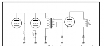
If you put the secondary of the IT in series with the cathode of the output tube then its anode current will flow through it. If the driver is SE too you might use the so-called inverted polarity which was first proposed (I think) by Shishido for pure class A2 amps where the DC current of the driver creates a a certain DC induction which is compensated by the DC current of the output tube (thanks to the inverted polarity. A bit like the PP transformer. So you would not need a big gap. Only a small gap to have some headroom in tweaking the operative conditions.
This is the original idea. You can see the black dot indicating the polarity of the winding.
This is the original idea. You can see the black dot indicating the polarity of the winding.
Attachments
The source impedance is based on the plate resistance and is in SERIES with the plate load and is used to calculated along with the leakage inductance to figure the High frequency POLE ...ie CORNER FREQUENCY...
The source impedance in parallel with plate load is used to calculate the Low Frequency POLE with respect to inductance.. The source impedance for Class A P-P is not the same as Class B P-P for the same given tubes and operating point... The source impedance for a Class AB and will flucuate between the Class A and Class AB value...
The source impedance in parallel with plate load is used to calculate the Low Frequency POLE with respect to inductance.. The source impedance for Class A P-P is not the same as Class B P-P for the same given tubes and operating point... The source impedance for a Class AB and will flucuate between the Class A and Class AB value...
Thanks for taking the time to answer. It's clear from both your answers that I haven't asked the question the right way. I need to think about it some more, perhaps do some tests , and then come back with the question phrased more clearly.
Thanks again!
Thanks again!
Would this simplistic approach work for determining the primary impedance of an unknown transformer?
Take a solid state amp with an output Z << 8 ohms, connect it to the 8 ohm secondary winding through an 8 ohm resistor. Use it to drive a sine signal into the transformer secondary of an appropriate frequency.
Load the primary with a variable resistor, say 10K. Reduce it until the impedance reflected through the transformer shows up as 8 Ohms on the secondary winding.
Then the AC voltage should be equal across the 8 ohm resistor and 8 ohm secondary winding. When this happens, the primary impedance should be equal to the variable resistor setting,
I could have this completely wrong. However, it's good to have a simple technique for determining the primary impedance of an unknown transformer. I'm sure OP's situation is very common - you're fortunate to have the units on hand, but know nothing about them - other than they're big, heavy and have a few taps available on the secondary.
Same thing with a finished commercial amplifier. Does the OEM ordinarily reveal the output transformer specs to that level of detail? What if you want to work on an amplifier you already own - but have no idea about primary impedance other than "must be something like" due to the output tubes being used.
I'd also like a proven technique to measure the VA capability of an unknown power transformer. Sometimes you have a perfectly good unit on hand - but have no idea what it can do for sustained current.
To find the Z pri of an unknown tfmr, first find the winding ratio by applying a 1khz sinewave of 1v say, measure V on the sec, next divide Vpri by Vsec, this is the winding ratio.
To find the Z ratio square the result, to find the reflected Z pri, times result by load. EG 1v RMS in pri, 0.1v out sec gives a winding ratio of 10. 10 squared is 100, so Z ratio is 100:1, an 8ohm load would give you a Z pri of 800r.
To find VA use the 10% rule using power resistors on the sec. first power up without load on sec, SW off, put R's on sec till you get a reading of about 10% unloaded, this should give you a rough VA. Then run tfmr for an hour or so loaded making sure tfmr isn't getting too hot, also if tfmr is buzzing this can be an indicator of overloading (or loose laminations).
To find which winding is pri/sec use a meter on resistance to get an idea. Both methods are ballpark ish.
Andy.
Rl would be the impedance the valve/s see. This is the load on the secondary reflected on the primary. If you put 16 ohms on a 8 ohm secondary for instance, Zpri or Rl is increased, put 4 ohm's on the same tapping , the Rl will be decreased.
Andy.
Andy.
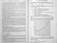
It is. I've put in the complete equation for someone interested in the effect of wire resistance on cut off frequency. That may set off the result for 10% or less, marginal I recon.
The decline of primary (reactive) impedance seems a gradual process of 6dB per octave and collides with the onset of phase shift. I wonder what would be permissable to aim for in a solid design, half a dB at 30Hz? Many speakers are almost silent at that point but all adds up..
The decline of primary (reactive) impedance seems a gradual process of 6dB per octave and collides with the onset of phase shift. I wonder what would be permissable to aim for in a solid design, half a dB at 30Hz? Many speakers are almost silent at that point but all adds up..
Last edited:
- Home
- Amplifiers
- Tubes / Valves
- Design based on the Output Transformer