I am interested in learning about this trick of yours.
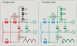
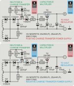
Trick works only if you have>X2 capacitance recommended, by inserting between PS caps a clever circuit which acts as a "gate" for charging currents. It was designed by -EC Designs- for low power circuits but it can be easily upgraded for high power increasing power rates for the active and passive parts.
It is called "Charge-transfer supply" and the negative rail uses inverted Schottkies and N Mosfet.
It cleans the soundstage and allows for better detail, IMHO. Only the first cap of cap bank receives the HF garbage when recitified V is at its peak; then when recitified V gets down, "gate" opens and first cap (cap bank) charges second cap (cap bank) and load; then cycle starts again (50-60hz or 100-120Hz, depending on country and diodes circuit) "gate" closes as rectified V increases and load only gets its current from the secondary cap(s).
I used this on efficient amps like class AB-B and UCD, so I don´t know if the values of the R should be modified for the F.O. since it is maybe more hungry...Ah and also on my VSSA..
Lots of work but worth it. 🙂
There is also a "floating charge-transfer" that I had only used on low power circuits...
Best wishes,
M.
Attachments
Two new FO amps!

Could you show us some more pics of an amp and system? Review with few sentences?
Could you show us some more pics of an amp and system? Same impressions after few days of listening?
Nice.Overall sounds are great.
Could you show us some more pics of an amp and system? Review with few sentences?
Great chassis layout, very low noise setup.Hello, here is my iteration of the 1.4
Could you show us some more pics of an amp and system? Same impressions after few days of listening?
Thats why I asked if I have to re calibrate it or not, but I am now working on re calibration.
Regards
It is obligatory to make calibration, as instructed in manual.

I have a trick for linear PS that I use in all my best amps...but lets hear what LC recommends as a minimum capacitance for 50 VDC...
Standard linear +/-63 V PSU, 20 mF per rail, 40 mF per channel. The only request is to have very low Z at mains transformer output which is not always the case. SMPS's primary elco bank is charged by low Z mains directly, energy transfer goes via HF transformer to secondary, we get current on demand whenever needed, so my recommendation goes to unregulated 50% duty-cycle SMPS.

To Hsi68.
LC runs mains wiring underneath the SMPS L shaped heatsinks...
To MetzB1,
The TX "center tap" Is one wire or two leads that go to the caps "ground"?
I think it is better to have a picture of the whole amp.
Good luck,
M.
Pic attached. Center tap not currently connected to chassis ground.
Attachments
Pic attached. Center tap not currently connected to chassis ground.
Classic stereo ground loop, one PSU for both channels with central GND between main caps. In this case everything has to be rearanged and connected to this central GND point, input GND and -SPK from both channels - GND star connections. Sadly at the end there will be no buzz/hum but also lower sound quality than with dual mono - two completely independent PSU - SMPS.
Appart that AC wires *mains/bridges* are too close to some DC wires. Have to keep more distance between them and organise, tweast them and wrap with plastic bonds.
The double center tap carries double current, forth and back to the center point, though there are short...
I would make star ground on the chassis and send all return currents there, even speaker-s return/ground, then to the center bar between caps. En mains earth could go there, or close. Some say it is important which ground/return goes nearer chassis and which ones must go on the top...go figure...
*sorry, de/configured keyboard*
Cheers,
M.
Extract from ESP - Power Supply For Amplifiers:
The centre-tap of the transformer and the ground points of each capacitor must be connected to the main signal earth point via heavy duty copper wire, or (preferably) a copper bus-bar.
Large currents flow in this part of the circuit, containing nasty current waveforms which are quite happy to invade your amplifier.
The supply voltages must be taken from the capacitors (not the bridge rectifiers) to prevent unwanted hum and noise.
Pic attached. Center tap not currently connected to chassis ground.
Hi, this amplifier topology (CFA) has very low power supply noise rejection (PSRR). It is then necessary to go all out in the power supply if you want to get the best out of it. You have mentioned that you have ground loop problem between channels. This can be solved with dual power supply like Lazy Cat did, which I think is a good decision.
May be more capacitance will help a bit, if another transformer is too expensive. Simple capacitance multiplier may help also...
Meanwhile, I don't know if it will make any difference, but I prefer to have both channels connected to one point (in the middle of the caps along with the secondary center tap) instead of left-channel from Cap1 and right-channel from Cap2.
BTW, I have tried a solution to separate left and right channels' grounds by using single transformer. I had to use 6 inductors including 2 for the channel grounds (it's CLC decoupling technique, including L on the ground). Transparency was very good, but the sound was not my "taste".
Jay, I don't know what are you talking about here?! This is commercial part of the forum, therefore your assumptions have nothing in common with First One v1.4 amplifier since you don't own one, nor know anything about its schematics. Please post your theoretical philosophy in some other threads in Solid state part of the forum, not here.
Schematic of FO v1.4 is light years ahead of what you know regarding CFA (FO v1.2), so please take my words seriously.
Regards, L.C.
Schematic of FO v1.4 is light years ahead of what you know regarding CFA (FO v1.2), so please take my words seriously.
Regards, L.C.
O'Stripper over in the Slewmaster thread has just made some developments that show that the oft spoken of shortfall with the CFA topology with psrr is not necessarily inherent in these designs. I don't know the circuit that LC is using in his FO1.4 but there is no reason to believe that it is absolutely necessary to talk of psrr ratio as being inferior to the VFA designs. Just more general talking points that can be overcome.
ps. LC, I sent you a PM about a week ago and don't know if you received that as perhaps your inbox was full. Let me know if you saw it, I would love to hear an answer to my inquiry, it doesn't belong here in your open forum.
ps. LC, I sent you a PM about a week ago and don't know if you received that as perhaps your inbox was full. Let me know if you saw it, I would love to hear an answer to my inquiry, it doesn't belong here in your open forum.
Just to be very clear, First One v1.4 modules works with single or dual power supply without any issues. Schematic in user manual is for dual power supply only, for a good reason since I want all builders to experience sound quality associated with it. All our listening tests in top notch audio systems showed big advantage of dual mono configuration compared to single PSU. We use sources and speakers not available to average DIY-er so you can trust our decision.
All amps I made so far are dead quiet, because of proper GND connections and high PSRR this amp has, so no worries here.
All amps I made so far are dead quiet, because of proper GND connections and high PSRR this amp has, so no worries here.
ps. LC, I sent you a PM about a week ago and don't know if you received that as perhaps your inbox was full. Let me know if you saw it, I would love to hear an answer to my inquiry, it doesn't belong here in your open forum.
Hi Kind
Spent few days on short Easter vacations, apologizing for delayed response. Will send you PM in short, thanks. 🙂
Thank you, LC. I can't do a dual supply as I don't have the components. I will star ground as you suggest. This amp will run two subs so hopefully, the single supply won't hurt performance too much in that application.
Classic stereo ground loop, one PSU for both channels with central GND between main caps. In this case everything has to be rearanged and connected to this central GND point, input GND and -SPK from both channels - GND star connections. Sadly at the end there will be no buzz/hum but also lower sound quality than with dual mono - two completely independent PSU - SMPS.
Hi LC,
Could you let me know how to connect the front panel LEDs with SMPS J4?
Also what kind of LED is good for?
TIA,
Sean
Could you let me know how to connect the front panel LEDs with SMPS J4?
Also what kind of LED is good for?
TIA,
Sean
Hi Sean
Very simple and effective task:
- J4, Pin_1, connect to anode of POWER LED
- J4, Pin_2, connect to chatode of POWER LED
- J6, take off short-jumper, solder 4,7 kOhm/0,5 W resistor to the pins where short-jumper was located on J6
Use any LED you like to be on the front panel. LED will get app. 4,6 mA, if it's still too bright use higher resistor value.
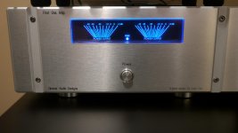
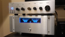
I finished my FO Amp - Still Very Impressed!!!
Well after a few more weeks I finally put the finishing touches on my FO amp. I added a speaker protection board and some eye-candy meters and a custom milled front panel. Still sounding impressive with a natural and transparent sound. You can hear every note executed with precision and clarity. This amp probably needs more break-in, but it's not fatiguing to listen to at all - regardless of genre. Sitting on top is my Doug Self 2012 preamp build I completed a few years back. It's a great match for the FO. 🙂
For those just joining the FO party, a few inside pics can be seen in my post here.
Rick
Attachments
Hi LC
any news about S version ?
I couldnt wait so I ve just order M version, but later I absolutely want to test biamping with 2 S. Any chance you could already post the drill plan for the S version please ?
in order to test I have only ordered 1 hypex 1200A400 and then I was thinking about why the hell it would be so much better with dual psu. In fact its all about the problem of the ground current return and the fact that wires are resistor and then a voltage is showing up. But to avoid any cross talk or interraction between signal and reactive load we just need a clean Star and connect the signal ground to the star point instead of the "in-" of the FO, right?? let see;
At the moment I m using a dual mono smps+classD amp from Audiopower (each 0V only connected to signal ground input) and the result is excellent
http://www.gopix.fr/image-E88F_56C0B9D5.jpg
but its too brilliant in the highs (may be thd)... I hope FO will solve that and that FO+Hypex will give the same clean and powerfull bass as this DPA400. Cheers
Last edited:
- Home
- Vendor's Bazaar
- First One - mosFET amplifier module