I have allready compleat measuring with digital bridge.
Prim is 0,5 ohms 36 mH 46 winds
Sec is 3,1L 450 H 5600 winds (26pF)
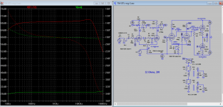
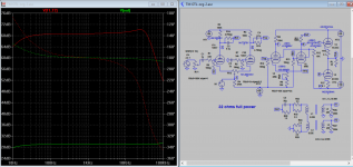
Can you trace 10hz -100Khz at 2w and full power 8 & 32 ohms ?
Also has to be counted the esl imput network R15/C25 and R1, R2
Let me know this is what you want or not, I'll redraw and sim now for 8 ohms
Attachments

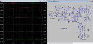
Here are the 8 ohms plots.
Attachments
Last edited:
Here are the 8 ohms plots.
This is very nice. Thak you.
One more thing if you can be pacient with me, as the purpose of those sims is finaly the influence of diffrent components on the final result, I'd like to ask you if possible, to change on 32 ohms sims the value of C25 from 220 uF to 56 uF as it has to be a constant (220x8 = 56x32)
I wonder also if the sec must or not to be loaded capacitiv..... as esl are mostly capacitive loads, they acts like capacitors.
What represent the dash lines on your diagrams?
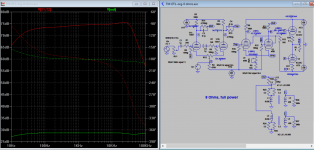
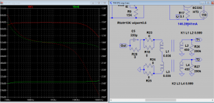
The plot is as attached, it's flatten a bit about 1Khz when 56u is used. The dash lines are the phase shift deg on the right vertical axis.
Regard the load resistor, it's value must be 200K or near to reflect 32 ohms to the amp output. I believe the final total load of all 3 ranges bass+mid+treble will end up in resistive load of 200k. The speaker itself is no doubt capacitive, external inductors resistor will bring them back to resistive. You can see the simplied diagram of ESL on Pg 173 here on Google book. I can plug in all these values in the simulation if you find one simplified circuit for ESL 63.
Edit: The peak above 10khz is due to the 26pf parallel winding capacitance you supplied.
Attachments
Last edited:
The plot is as attached, it's flatten a bit about 1Khz when 56u is used. The dash lines are the phase shift deg on the right vertical axis.
Regard the load resistor, it's value must be 200K or near to reflect 32 ohms to the amp output. I believe the final total load of all 3 ranges bass+mid+treble will end up in resistive load of 200k. The speaker itself is no doubt capacitive, external inductors resistor will bring them back to resistive. You can see the simplied diagram of ESL on Pg 173 here on Google book. I can plug in all these values in the simulation if you find one simplified circuit for ESL 63.
Edit: The peak above 10khz is due to the 26pf parallel winding capacitance you supplied.
This is (26pF) what I get on the bridge while measuring the sec. I am not shure it is right or not. In any case it is out of audible spectrum.
An other simplified diagram then the previeus already attached I don;t have and in any case the values of the coils are unkown.
Regarding the 56uF cap, I was expecting to change the lower frequency range under 100 hz. Nevertheless I'l change the 220 uF cap with a better MKP one as the original is electrolith bipolar and old enagh.. Thanks again.
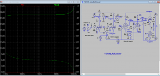
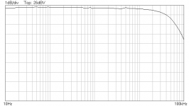
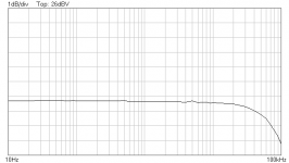
Just for purpose of sim, I remove all the added components of the 2 transformers, and 26p, the bass bottom is much improved. Is that something you can try?
Attachments
Just for purpose of sim, I remove all the added components of the 2 transformers, and 26p, the bass bottom is much improved. Is that something you can try?
Ies, it is mor like what I get in practice, but I think R28, 25, 24, 23, 18 must be mantaind as they exist on the original esl circuit.
Attachments
Looks good! If I can make a recommendation, after you've sorted out where all the holes go, take it to a finishing shop to get it painted or anodized. With that much work its nice to make it look nice too.
Thanks, atmasphere. I think anodizing would be my preference.Looks good! If I can make a recommendation, after you've sorted out where all the holes go, take it to a finishing shop to get it painted or anodized. With that much work its nice to make it look nice too.
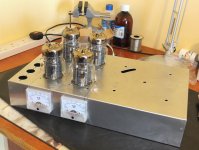
I'm making good progress with the chassis, as this mock-up shows:
Nice work, bravo.
I've just realized that Tim Mellow specifies a steel chassis. I'm using alum; I wonder does it matter. Steel can short circuit stray magnetic fields.
I've just realized that Tim Mellow specifies a steel chassis. I'm using alum; I wonder does it matter. Steel can short circuit stray magnetic fields.
I use 2mm aluminum chassis, I have 2 large 300VA transformers mounted under the chassis, on top is pre-amp and output PCB, I don't find any problem. The residual hum level comes from the power supply.
You can put small extra sheet between the chassis and transformer to act as both bracing and shield, I think if it is steel and 1mm there would be some vibration or humming noise or thump when power on. Be careful not to short the middle mounting screw, ie can not connect both end to ground.
Last edited:
When I first started in on tube amps, I was tinkering with old amps and I saw many steel chassis with no discernable effect on the sound.
I use 2mm aluminum chassis, I have 2 large 300VA transformers mounted under the chassis, on top is pre-amp and output PCB, I don't find any problem. The residual hum level comes from the power supply.
Koonw, how loud is the "residual hum" in your amp?
Koonw, how loud is the "residual hum" in your amp?
About <2mV , on 5mV*10 scale scope, it's low ripple (can not hear even press again the speaker.
About <2mV , on 5mV*10 scale scope, it's low ripple (can not hear even press again the speaker.
RIGHR, no noise at all.....sometimes I'like to hear a little HISSS, but there is no hiss ... nothing.
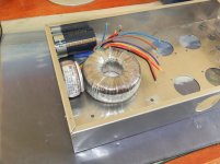
I'm almost ready to do the wiring. This is a preliminary fit-up of one of the main smoothing capacitors as well as T1 and T2. I have used just one capacitor of 4400uF 250V for each side of the 150V supply. They are high quality Panasonic from Digi-Key. T1 is a budget item and is very unevenly wound, so I had to use thick vinyl floor-covering instead of the stock neoprene rubber. It takes up the undulations in the winding very nicely.
Attachments
Do yourself a favor- when mounting the transformer, avoid using a steel bolt. Instead use a stainless non-magnetic bolt (but don't use a stainless net to secure it!!). You will find that the transformer runs cooler.
- Home
- Amplifiers
- Tubes / Valves
- New Tim Mellows OTL project