I wouldn't think so G. Ceramics don't expand and contract nearly as much as metals do. I've seen many many many amps without them. You should be fine.
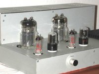
I like that chassis. What side is going to be the front? I like to see tubes standing front and center just cuz they look cool.
Thanks for that advise, djn. I haven't decided on the final layout yet. I agree with the aesthetics of having the tubes standing front and centre but I'm limited by the size of the 3 transformers I'm using. Hopefully they will arrive here in the next hour and then I will have a better idea.
I understand that G. Luckily I am using 2 chassis so I have plenty of room for my PS. The issue I am trying to work through is trying to make 2 AZ1 rectifier tubes work instead of the diode bridge.
For two full wave rectified supplies, I think I am right in saying that you would need 4 of them.
For two full wave rectified supplies, I think I am right in saying that you would need 4 of them.
I forgot that AZ1 is a double rectifier, but it has a common cathode.
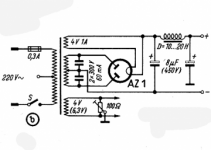
I don't think it's essential. It could have something to do with suppressing noise.Why is there 2 caps going from the leads to the center tap before the rec tube in this pic??? I've never seen that before.
Could someone please advise me if it is necessary to use fiber washers up against the tube bases to take into account the expansion when they get hot. None of the fiber washers that I have looked at will tolerate any greater than 100° C, so maybe it isn't an option anyway.
The usual practice is to use Teflon washers, that is if you are mounting the socket beneath the chassis surface. The idea is to space it slightly to increase air flow.
Question to the group.
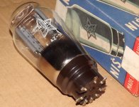
Can I make make 2 AZ1 rectifier tubes work instead of the diode bridge. This is just for aesthetics mind you, but I've had these tubes and sockets sitting in my stash for 8 years now and just like the looks of them.
I don't think vacuum tube rectifiers are well suited to an OTL amplifier. You need HT supplies that are capable of providing currents of order 1 amp or more (at peak volume), not milli-amps, and you don't want the voltage to drop substantially when the current draw rises to these rather substantial values.
Chris
I am wondering is it OK to surround the two concentrically mounted transformers, T2 and T3 with an enclosure. Would heat build-up be a problem if the box was totally enclosed?
The heat would build up with just the 6c33c alone. If you mount a 12V dc fan runs on 6V or so, on bottom chassis that blows air upwards, thus allows stream of air to flow out the top through all tube spaces, cool off the tube as well as any heat (transformers, capacitor etc) inside the enclosure. This is more effective than a sucking fan which tends to suck hot air inside from top where the tubes are.
Last edited:
Thank, Koonw. What spacing from the chassis do you suggest for the tube bases?The heat would build up with just the 6c33c alone. If you mount a 12V dc fan runs on 6V or so, on bottom chassis that blows air upwards, thus allows stream of air to flow out the top through all tube spaces,
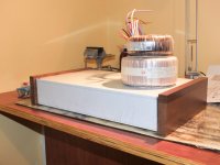
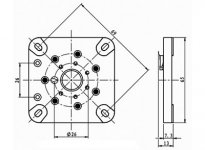
If you mount the socket under the chassis, 3-5 mm is enough, the socket itself has about 1 mm of spacer at the 4 corners. You can go down as far as you can if you cut the opening bigger than the tube glass base which is about 52 mm diameter and hole 55 mm so space of tube to chassis is about 2-3 mm (not to cut too big). You use a hand turn hole punch to make the real clean cut esp on steel.
Attachments
Last edited:
If you mount the socket under the chassis, 3-5 mm is enough, the socket itself has about 1 mm of spacer at the 4 corners. You can go down as far as you can if you cut the opening bigger than the tube glass base which is about 52 mm diameter and hole 55 mm so space of tube to chassis is about 2-3 mm (not to cut too big). You use a hand turn hole punch to make the real clean cut esp on steel.
Similar to attached.
Attachments

Last edited:
Thanks, Koonw. That is just what I wanted to see. There's plenty of space around the tubes in those photos. I won't cut the holes until the tubes arrive from Russia. The last known location was Saint Petersburg and they haven't moved from there for a good while.
I am wondering is it OK to surround the two concentrically mounted transformers, T2 and T3 with an enclosure. Would heat build-up be a problem if the box was totally enclosed?
I wonder if there would be interference between the two transformers? Maybe a grounded copper sheet between them would mitigate it.....if there is any.
You might want to cut a hole for a fan then see if it gets hot enough to actually mount one and yes, if you run it at 6v, you won't hear it.
I wonder if there would be interference between the two transformers? Maybe a grounded copper sheet between them would mitigate it.....if there is any.
You might want to cut a hole for a fan then see if it gets hot enough to actually mount one and yes, if you run it at 6v, you won't hear it.
The two fields are self contained within the individual torus, as far as I know.
If you are mounting on atop the other (one on top of the chassis, one on the bottom) they could talk to each other and heat up a bit. You can reduce this by reversing the phase on the primary winding of one of the transformers.
PSU Cap revisted
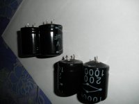
Sometimes ago I reported this problem, and I have put in a new set of 8 pcs same NOS 1000u/200V. After 4 months of use I discovered 4 were budging (one is opened circuit) C5-C8, all after R1 and R2 which is 1 ohm each maybe this is causing too high rippled current and thus heat causing the budging. The other 4 C1-C4 are still reasonably good, after replace another 4 nos cap, I also drop R1/R2 to zero ohm. I hope to see what happens in next few months.
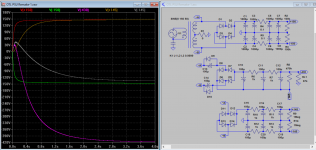
Attached is also the remake of PSU, if I were to build TM amp or others where -430V and +145 is required, their AC input are derived from same transformer for the +-150V. If +-150V rail dropped to +-140V at full power, the -430V and +145V would also drop and thus maintained the almost same bias level for top and bottom. The advantage over the original is that it output level is depended on transformer power output drop instead of voltage of -150V rail, which is too rough a ride IMO for the bias. And beside the bias would not change very much should there be a problem with the bottom tube and -150V rail. If you are to build independent supply for -430V, the bias level for the tubes would be out when the power output varied. So just a note for those who I have advised in private mail, I will just post this for all to see.
Sometimes ago I reported this problem, and I have put in a new set of 8 pcs same NOS 1000u/200V. After 4 months of use I discovered 4 were budging (one is opened circuit) C5-C8, all after R1 and R2 which is 1 ohm each maybe this is causing too high rippled current and thus heat causing the budging. The other 4 C1-C4 are still reasonably good, after replace another 4 nos cap, I also drop R1/R2 to zero ohm. I hope to see what happens in next few months.
Attached is also the remake of PSU, if I were to build TM amp or others where -430V and +145 is required, their AC input are derived from same transformer for the +-150V. If +-150V rail dropped to +-140V at full power, the -430V and +145V would also drop and thus maintained the almost same bias level for top and bottom. The advantage over the original is that it output level is depended on transformer power output drop instead of voltage of -150V rail, which is too rough a ride IMO for the bias. And beside the bias would not change very much should there be a problem with the bottom tube and -150V rail. If you are to build independent supply for -430V, the bias level for the tubes would be out when the power output varied. So just a note for those who I have advised in private mail, I will just post this for all to see.
Attachments

Last edited:
- Home
- Amplifiers
- Tubes / Valves
- New Tim Mellows OTL project