[QUOTE 18W, just before clipping of either tube, THD around 0.4%.
Please compare distortion at lower output power like 1W then if the model is reasonably correct you should see larger differences, the differences in distortion you see at clipping probably are more due to difference in output power.[/QUOTE]
See attached.
Attachments

See attached.
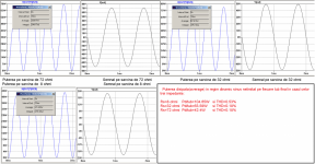
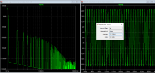
I assume that the left picture is for unmatched case?
Yes, that is what I would expect, see all the higher harmonics on the left, I normally see a spectrum close to the right one but we match tubes very close so 2nd order is much lower than 3rd.
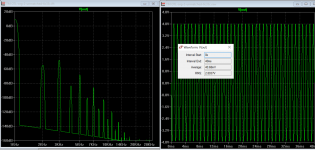
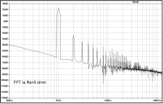
This is what my coleg ha sim for my project, then what I have captured "live" at 25W/8ohm and 1w/8ohm
The sim was on perfect matched tubes
The "live" capture was my otl as it is with random chused 6c33c, only EF86 was 10% matched
The sim was on perfect matched tubes
The "live" capture was my otl as it is with random chused 6c33c, only EF86 was 10% matched
Attachments

Last edited:
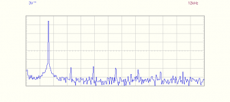
what I have captured "live" at 25W/8ohm and 1w/8ohm
As I am building OTL amplifiers for sale I should be careful not to promote my own amplifiers.
Let me just say that the spectrum at 1W is far from ideal, higher harmonics are at similar level as 2nd and 3rd which they shouldn't be, I would expect to see only 2nd and 3rd and the rest down in the noise.
It is important to optimize performance at low level as that is where the amplifier will be used most of the time, with a 25W amplifier you would never have an average power higher than 1W
I assume that the left picture is for unmatched case?
Yes, that is what I would expect, see all the higher harmonics on the left, I normally see a spectrum close to the right one but we match tubes very close so 2nd order is much lower than 3rd.
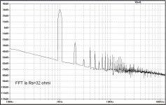
Are you sure it's only matched tube? How about 100% NFB to plate of bottom tube ef86 driver, isn't is a bit skew as it corrects the lower tube more than upper? If you connect the plate resistor of lower tube to the ground instead to output, you see a quite different pattern. This more like conventional bootstrapped correction, but you can read my earlier post about the remake where the FFT pattern is different.
Are you sure it's only matched tube?
I can not speak for the Mellows design as I am making a different type of OTL, I think I know why the 2nd is higher than 3rd in this design but I prefer not to comment on other peoples design as I am commercially involved.
I can not speak for the Mellows design as I am making a different type of OTL, I think I know why the 2nd is higher than 3rd in this design but I prefer not to comment on other peoples design as I am commercially involved.
Not problem, how do we know that, to me any member here is considered diy forum family.
how do we know that
It is mentioned in my profile, I don't want to mention it any other way as I can be banned for making commercial promotion.
It is important to optimize performance at low level as that is where the amplifier will be used most of the time, with a 25W amplifier you would never have an average power higher than 1W[/QUOTE]
So, what shall I do?
So, what shall I do?
So, what shall I do?
Start by matching tubes, as Koonw has simulated the higher order products will be reduced when using matched tubes, in my experience the sound will be softer and less solid state like when the higher order products are lowered.
Try to find tubes that have same grid voltage +-1V when measuring at the idle operating conditions.
Even though my OTLs are different than Mellows the conditions are similar, most distortion comes from the output tubes so that is where you should put most effort.
Thanks, do you think the matching "engine" from thred #332 shall be helpfull?
Do you think ccs at the first stage shall help ?
Matching can easily be done by just measuring grid voltage at a given current, you don't need anything more complicated.Thanks, do you think the matching "engine" from thred #332 shall be helpfull?
Do you think ccs at the first stage shall help ?
CCS or not has no measurable effect on distortion, most comes from output tubes.
Try to find tubes that have same grid voltage +-1V when measuring at the idle operating conditions.
Tubevtr, could you be a bit more specific in what you mean by that. I'm a bit lost. Thanks
In Mellows design he use 150V anode voltage and an idle current of 200mA, set up a source of 150V with a variable source for connecting to the grid and adjust grid voltage so that anodecurrent is 200mA, note grid voltage value, then do the same for other tubes. select the tubes that have similar grid voltage.Tubevtr, could you be a bit more specific in what you mean by that.
In Mellows design he use 150V anode voltage and an idle current of 200mA, set up a source of 150V with a variable source for connecting to the grid and adjust grid voltage so that anodecurrent is 200mA, note grid voltage value, then do the same for other tubes. select the tubes that have similar grid voltage.
Thanks. Will I leave out any plate resistor.
No plate resistor, just tube and 2 voltage sourcesThanks. Will I leave out any plate resistor.
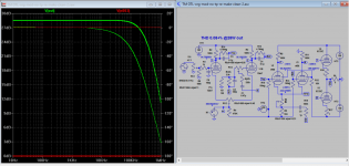
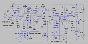
Hi, after you guy have finished with Tim's original, you can have a look at complete remake sch here for some clues if you want improvement. I also somewhat remade my own otl amp that use 6c19, the sch is very similar to remake attached here and sound and distortion has improved. A little positive feedback can cut down THD to very low level.
Attachments
Last edited:
No plate resistor, just tube and 2 voltage sources
Great thanks. That seems like a walk in the park as they say in the US. I have some unmatched 6C33Cs coming from Russia in the next day or so. Before I wire up my amp, which I haven't started yet, I'll build the PSU circuit first and use the +150V for the HT and the -150V with a pot for the grid bias.
Hi, after you guy have finished with Tim's original, you can have a look at complete remake sch here for some clues if you want improvement. I also somewhat remade my own otl amp that use 6c19, the sch is very similar to remake attached here and sound and distortion has improved. A little positive feedback can cut down THD to very low level.
Verry interesting, did you listen to it? In which way the sound has been improoved?. How could you manage to tune so many variable ponts and no capacitors in the imput link.
Verry interesting, did you listen to it? In which way the sound has been improoved?. How could you manage to tune so many variable ponts and no capacitors in the imput link.
Yes, my own otl amp is about 10 years old, and phase spliter is concertina, I use PF for a long time. When I switched to LTP, the sound is less congested, and finally settled for Bejing 6N2 and Russian 6N1P(driver).
All you need is scope, Rpfb simply adjusted for damping and harmonics will be lower just approach over-damp point.
You can temp short the input while adjusting bias, once settle it's zero voltage. The NFB to driver is neccessary only of 32 ohms load or more. In my own amp I have trimmer on 2nd LTP cathode also for AC bal. good for unmatched tube, it really cut down odd harmonic. But you can't do that with Tim amp because it will affect bias of output tube. Since you have caps between LTP1 and LTP2, direct coupled has little advantage and you can redesign the LTP2 to bias just the the same. There too many DC in his design, a small variation at the output can affect LPT2 esp when high output level.
- Home
- Amplifiers
- Tubes / Valves
- New Tim Mellows OTL project