There are several TPA3116 "2.1" boards you could use. The ".1" channel has the L-R summer and the LP filter. The LP filter can be "bypassed" into full-range by replacing two capacitors.What about the 2.1 board version of the TPA3116/3123?
A second 31xx chip is bridged to deliver a twofold increased output for the subwoofer. One could possibly use the (mono) subwoofer channel as a center channel when one would be able to somehow remove the low pass filter. This solution would be sufficient I think for my 3-channel radio project.
What remains is the more elaborate 3-channel stereo for my living room setup. Ideally the 3 channels are connected with each other in a so called 0.5 matrix which requires a common ground.
As for bridging ... each channel of the TPA3116 is already "bridged" in the chip as in Bridge Tied Load (BTL). This gets the maximum power out for a given Vcc supply voltage and speaker impredance.
The sub channel on most of these boards parallels the two output channels of the second chip into PBTL (Parallel Bridge Tied Load). You don't get any more power out for a given Vcc with the same speaker. However, paralleling the output allows you to use a speaker of lower impedance (e.g., 2 ohms instead of 4). With the lower impedance speaker, you get more power for the same Vcc.
The summer on the sub channel will have gain as Subs usually require more power to match the level of the L-R channels. However, these boards have separate volume controls for the sub, L-R and overall volume so match the center to the L-R output would be easy.
@millstonemike
Bridging of the TPA3116 clearly explained.
This TPA3123 2.1 board I bought on eBay is underway for my 3-channel radio project.
http://www.ebay.com/itm/221799166668.
It is, as you probably know, a lower power version of the TPA3116.
Would you be able to identify the low pass filter components on this board?
If so, could I just shortcut/replace these filter C/R to get the full frequency range?
Bridging of the TPA3116 clearly explained.
There are several TPA3116 "2.1" boards you could use. The ".1" channel has the L-R summer and the LP filter. The LP filter can be "bypassed" into full-range by replacing two capacitors.
This TPA3123 2.1 board I bought on eBay is underway for my 3-channel radio project.
http://www.ebay.com/itm/221799166668.
It is, as you probably know, a lower power version of the TPA3116.
Would you be able to identify the low pass filter components on this board?
If so, could I just shortcut/replace these filter C/R to get the full frequency range?
@sharpi31
This is an interesting idea. I am not shure that I can follow you one hundred percent on this, especially regarding the transformer part. Could you please illustrate your proposed circuit in a diagram for a non-electronic engineer like me?
http://www.jensen-transformers.com/wp-content/uploads/2014/08/as065.pdf
Last edited:
221799166668-@millstonemike
Bridging of the TPA3116 clearly explained.
This TPA3123 2.1 board I bought on eBay is underway for my 3-channel radio project.
[URL="[/URL]
It is, as you probably know, a lower power version of the TPA3116.
Would you be able to identify the low pass filter components on this board?
If so, could I just shortcut/replace these filter C/R to get the full frequency range?
This layout of this board is significantly different than mine. You can see the traces but you really need to "buzz it out" to reverse engineer it. I can tell you this, the high level design is likely the same as my board. That is, there's a quad op-amp on the board (I had two dual amps). Likley, this is where the L-R summer, sub gain and LP filter are implmented. The low pass filter is probably a Sallen-Key topology as its the current standard in 2nd order filter design for consumer electronics.
If you have MS-PowerPoint, I could let you have my schematic. You could overwrite component numbering from your board's silkscreen legend by buzzing out the circuit. Effectively reverse engineer your board.
Trying to find the caps experimentally unfortunately requires the trial and error removal of some SMT caps near the quad op-amp (C7 thru C12?). Two of them are the LP filter caps.
Has anyone tried any of HiAmplifier's boards? I was about to jump into the YJ Blue/Black modding bandwagon when I found them mentioned in a post here.
http://www.ebay.com/itm/TPA3116-Class-D-2-0-Stereo-Power-Amplifier-Board-Nichicon-and-Solen-MKP-Cap-/121353266203?hash=item1c4137e41b:g:L~sAAOxyF0pTih1b
http://www.ebay.com/itm/TPA3116-Class-D-2-0-Stereo-Power-Amplifier-Board-Nichicon-and-Solen-MKP-Cap-/121353266203?hash=item1c4137e41b:g:L~sAAOxyF0pTih1b
Last edited:
This layout of this board is significantly different than mine. You can see the traces but you really need to "buzz it out" to reverse engineer it. I can tell you this, the high level design is likely the same as my board. That is, there's a quad op-amp on the board (I had two dual amps). Likley, this is where the L-R summer, sub gain and LP filter are implmented. The low pass filter is probably a Sallen-Key topology as its the current standard in 2nd order filter design for consumer electronics.
If you have MS-PowerPoint, I could let you have my schematic. You could overwrite component numbering from your board's silkscreen legend by buzzing out the circuit. Effectively reverse engineer your board.
Trying to find the caps experimentally unfortunately requires the trial and error removal of some SMT caps near the quad op-amp (C7 thru C12?). Two of them are the LP filter caps.
I'm afraid that reverse engineering is way out of my league.
Alternatively, I could buy another board similar to yours and, together with your schematic and the info you provided, it might help me further to figure out how to eliminate the low pass filter.
Could you please let me know your board details and the MS-PowerPoint scheme?
This diagram clarified a lot for me regarding the text of your earlier post #9114.
After looking it over I am not so shure that, as it is now, you can accomplish an optimal 3-channel matrix system with it before amplification by TPA3116. On the other hand it also offers opportunities for modification and to utilize well sounding cheap amplifiers like the TPA3116.
Since I would like to further discuss this system, and because it is somewhat off-topic, we may continue the discussion in another thread such as for instance the sleeping 'Making 3 front channels out of stereo signal' if you agree.
tpa3123 isn't a low power version of the 3116
I consulted the datasheet of the Texas Instruments TPA3123D2. It states:
"The TPA3123D2 is a 25-W (per channel) efficient, Class-D audio power amplifier for driving stereo speakers in a single-ended configuration or a mono speaker in a bridge-tied-load configuration."
So, the nominal power output is clearly lower than that of the TPA3116 (50W per channel nominal/4Ohm). One of the differences is for me surprisingly very interesting, namely the single-ended configuration of the stereo channels, in contrast to the BTL of the TPA3116. Whether the single-ended channels also have the required common ground remains to be verified when my TPA3123 board arrives.
To be entirely correct, the TPA31xx family consist of TPA3116 (50W/ch/4Ohm), TPA3118 (30W/ch/8Ohm) and the TPA3130 (15W/ch/8Ohm), but all of you , except me, knew that of course.
Last edited:
If you want to compare to 5 year older chip, 3116/18 are stereo btl, tpa3123 is mono, both classD and btl power into 8 ohm is comparable, same brand, not much else is comparable, obviously.
I have purchased from Hiamplifier, some of his smaller design 3116 boards, the smaller squares, @$35/each, which can be easily modded to mono.
http://www.ebay.com/itm/TPA3116-Cla...927725?hash=item1c3dbdb76d:g:3aYAAOxydgZTIzbi
They sounded fine, although I did not play with them much.
I can say this, he is a more conscientious ebay seller than most, included a schematic, complete set of gain resistors, and instructions with his boards. He forgot to send the gain resistors with one purchase, and he actually sent another package which included them.
So, if you feel it worth it to spend the few dollars more for his boards, I think they are just a bit better value, given his commitment to customer service.
I just haven't played/listened to the stereo 3116 boards I got from him very much.
I'm afraid that reverse engineering is way out of my league.
Alternatively, I could buy another board similar to yours and, together with your schematic and the info you provided, it might help me further to figure out how to eliminate the low pass filter.
Could you please let me know your board details and the MS-PowerPoint scheme?
Here's an eBay link to the board I have:
YJ TPA3116 2 1 2 50W 100W Class D Amplifier Completed Board | eBay
This is a different seller. The one I used no longer carriers the board.
Beware a similar board:

Notice the three large PS decoupling caps instead of the one cap as on the linked board. This is the same basic design. However, another user experience significant problems with wrong parts populated on the board (different mfg?).
Here's the mod. Remove the two blue caps I've circled in red. That will defeat the LP filter.

I would like to thank everybody who responded to my initial questions in post #9111.
Great thread, great forum.
I have learned a lot from the discussions that helped me to proceed with my hobby projects.
Back to the soldering iron then, keeps ones mind off the angry world outside.
Kornelis
(retired scientist, 73y)
Great thread, great forum.
I have learned a lot from the discussions that helped me to proceed with my hobby projects.
Back to the soldering iron then, keeps ones mind off the angry world outside.
Kornelis
(retired scientist, 73y)
Kor010, you should consider a mini-dsp and active speakers.
One of those sanwu-3118-pbtl or sanwu-TDA8932-btl boards built into each speaker and the dsp will do the crossover and eq part.
One of those sanwu-3118-pbtl or sanwu-TDA8932-btl boards built into each speaker and the dsp will do the crossover and eq part.
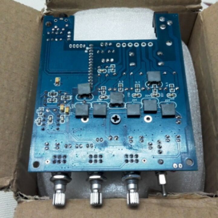
Hi guys...I am having a problem with new board. At full volume and havy bass it shuts (quiets) down for a moment. This is a latest model of 2.1. I haven't had any problems with my previous model of same board.
Here is the picture of new board
https://www.dropbox.com/s/h1pgobz73le3osj/20160327_084629.jpg?dl=0
and the old one...
https://www.dropbox.com/s/gzrqn45n7fi685f/UT8g89HXxJXXXagOFbXo.jpg?dl=0
I see the main difference is that the older had 3 main capacitors of 2200uf and the new one has 2x3300mf + a smaller 220uf on the middle.
Anyone has idea what is the problem and how to fix it?
Thanks
update...I just remembered I have a damaged red yj board with black 10000uf capacitors....have connect them from the back to first cappacitor and looks like the problem is fixed. So probalby the capacitors are too week?
update...well the problem still exists.
Few more details...L+R chanels are runing two 8ohm FR on paralell...sub chanel runs 4ohm sub + 8ohm midbass on paralel. Power supply is 24v 6A. Board spec says that L+R can run 4-8ohm, sub 2-8ohm...and as mentionted the older model of same board handled it easily, but this one can't. I ordered several pieces of this board for this project and now I am strugling what to do.
Anyone has an idea where is problem...please 🙂
Sounds like thermal shutdown or current overload shutdown. The chip is smart and self protects - although the answer is to shutdown so hard to find what is causing it. I have seen this happen at high volume when driving a large pro audio driver that can handle hundreds of watts. It just wasn't meant to drive big heavy loads - you may have an impedance spike (due to tuning of box) near where bass notes are. If you have an O-scope, measure the peak voltage output when shutdown occurs, If you are driving more than 90% of rail voltage, that will do it.
The ampboards are completely different, one can play two times louder than the other and switch off. PSU might be 25.3V or even higher which can be a problem for one and not for the other. All new boards act the same?
Both sub and mainchannels so two independant tpa's switch off/mute at exact same moment ?
Both sub and mainchannels so two independant tpa's switch off/mute at exact same moment ?
- Home
- Amplifiers
- Class D
- TPA3116D2 Amp