

Hi xedox,
I've been on holidays for the past few weeks (one week to go) so haven't done much work on the project aside from a lot of listening.
I plan to get straight back into working on completing the PCB once holidays are over.
It shouldn't take too long to make the final modifications.
Thanks for enquiring.
🙂
Ryan
Populated and tested PCB interest?
Hi All,
Anyone interested in a populated and tested Distinction-V2 PCB? (minus the TDA1541A chip)
If you are interested please cut and paste the list and add a hash (#) next to your name on the interest list thread.
No promises at this stage, it will depend on how busy I am at work etc.
No commitment if you put your name down at this stage. Just want to get a rough idea of the interest out there.
Cheers.
Update.
Hi Guys,
I've been back at it this week, tweaking and making small changes to the board.
One not so small change was the removal of the re-clocking section. While it did function ok in testing, I realised it may not be the ideal solution for most users. The digital PSU and the resistive attenuators still remain.
Small mods:
-LEDs added
-Ferrite beads 600Z.
-Removal of 22uF film - caused instability (as simulated...)
-CAP footprint change F to G size.
-AOL, AOR trace size increased.
-Schematics cleaned up and part descriptions added.
Still a few other things that need to be done but getting close.
Cheers,
Ryan.
Interesting.
Hi All,
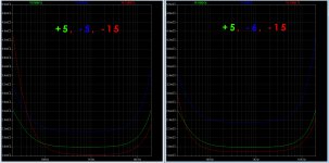
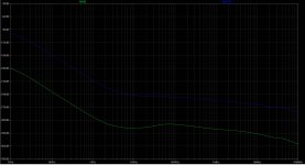
Just wanted to share this comparison between two slightly different PSU configurations.
In the pic attached there is a side by side comparison between -15,-5, and +5 VS -15, -6, and +5.
In this configuration with the stacked -6 and -9v(-15V referenced to ground) regs, the output Z for the -15V seems much better at the lower frequencies but at the cost of lower performance for the -6V reg.
A bonus is less heat dissipated on the -15v PNP pass transistor (940mW vs 790mW).
This idea is based on the fact that a lot of philips CD players had -6V instead of -5V (from what i've read on the net). Looks like its worth trying anyway.
Ryan
Hi All,
Just wanted to share this comparison between two slightly different PSU configurations.
In the pic attached there is a side by side comparison between -15,-5, and +5 VS -15, -6, and +5.
In this configuration with the stacked -6 and -9v(-15V referenced to ground) regs, the output Z for the -15V seems much better at the lower frequencies but at the cost of lower performance for the -6V reg.
A bonus is less heat dissipated on the -15v PNP pass transistor (940mW vs 790mW).
This idea is based on the fact that a lot of philips CD players had -6V instead of -5V (from what i've read on the net). Looks like its worth trying anyway.
Ryan
Attachments
Last edited:
Hi all,
Just would like to say that for those of you using the TDA1541 for 48 kHz or 96 kHz reproduction (or maybe a PCM1704) there's a 6.144 MHz crystal available in the "The Well Tempered ... " thread:
http://www.diyaudio.com/forums/digi...ow-phase-noise-jitter-crystal-oscillator.html
We have been able to get a quote on a low No. of crystals, however, it would be feasible if one - or more - of the diyaudio members were interested in buying one.
Price for this particular crystal - due to the relatively low Nos currently on order - will be 44 EUR + shipment from Italy to where you may be.
FYI I've been told that the frequency range around 5 MHz should be the sweet spot for lowest phase noise from a crystal (please don't ask me any specifics, though, as this is not my most knowledgeable field).
If you are interested then please send me a PM ASAP as the group buy is closing very shortly (a few days).
Cheers,
Jesper
Attenuation simulation.
Hi All,
One last experiment before I commit to the final design.
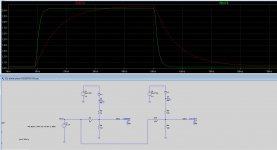
The level of noise on the 3.3V reg was a little much for my liking, so i've modified a few values and added a ferrite bead to supply the reference voltages.
The trace in red is the scenario I will try for DATA L, DATA R and BCK. The trace in green is what i'll apply for LE (sample is triggered by LE in simultaneous mode). Note that if I was running in I2S i'd have BCK with the green trace (triggers the sample in I2S mode).
The idea for applying a much slower rise time for DATA L, DATA R and BCK is simply to minimise polluting the surrounding circuitry with high frequency noise, this includes power supplies and leakage into the substrate of the 1541a. These inputs are not as important in terms of timing, so long as they make it to the shift register when the sample is triggered.
Cheers.
PS. Ive installed a new clock using a citizen crystal (11.2896), The PCB is by Anton (amc184) Click here to check it out. Andrea Mori took some measurements of phase noise - better than the craptech 957. Im liking what im hearing with this new clock...
Hi All,
One last experiment before I commit to the final design.
The level of noise on the 3.3V reg was a little much for my liking, so i've modified a few values and added a ferrite bead to supply the reference voltages.
The trace in red is the scenario I will try for DATA L, DATA R and BCK. The trace in green is what i'll apply for LE (sample is triggered by LE in simultaneous mode). Note that if I was running in I2S i'd have BCK with the green trace (triggers the sample in I2S mode).
The idea for applying a much slower rise time for DATA L, DATA R and BCK is simply to minimise polluting the surrounding circuitry with high frequency noise, this includes power supplies and leakage into the substrate of the 1541a. These inputs are not as important in terms of timing, so long as they make it to the shift register when the sample is triggered.
Cheers.
PS. Ive installed a new clock using a citizen crystal (11.2896), The PCB is by Anton (amc184) Click here to check it out. Andrea Mori took some measurements of phase noise - better than the craptech 957. Im liking what im hearing with this new clock...
Attachments
Last edited:
Update.
Hi All,
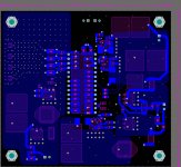
Distinction-1541 v2 is nearing completion.
I've added a 3.3mH inductor to the digital supply to be part of the current setting element, same as zenner string.
Added an extra cap to each power rail to bring impedance down past 100k (~5mohm).
Squeezed in 1210 footprints for pins 12,13,18, and 19 (MSBs)
Over the next few days i'll order one last prototype PCB to verify the changes I've made (not major changes, but i'd kick myself if there was an issue with 100 PCBs...).
Ryan
Hi All,
Distinction-1541 v2 is nearing completion.
I've added a 3.3mH inductor to the digital supply to be part of the current setting element, same as zenner string.
Added an extra cap to each power rail to bring impedance down past 100k (~5mohm).
Squeezed in 1210 footprints for pins 12,13,18, and 19 (MSBs)
Over the next few days i'll order one last prototype PCB to verify the changes I've made (not major changes, but i'd kick myself if there was an issue with 100 PCBs...).
Ryan
Attachments
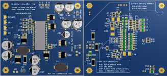
How ironic that I left the "g" out of knowledge on the PCB...😱
No spell checker in altium?! grrr.🙄
No spell checker in altium?! grrr.🙄

Hi Ryan,
can you post a necessary part list?
what about the psu? what is your proposal?
many thanks
can you post a necessary part list?
what about the psu? what is your proposal?
many thanks
Very nice work indeed!
Congratulations!
Thanks for the kind words. 🙂
Hi Ryan,
can you post a necessary part list?
what about the psu? what is your proposal?
many thanks
Part list soon to come, just have to go through it again and make sure all is well. I will have time over the next few days.
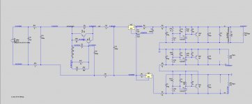
For the PSU- I'll attach a simulation I've been working on. It's a basic schottky rectifier, CRC then to a Capacitance multiplier (kean tokens K-multiplier) + RC. Ripple rejection by the k-multiplier on its own simulates at around -60dBv. The k-multi has been reported measure very close to these specs. Not too bad for such a simple, clever little circuit. Output impedance will be about 50 mohms at 120mA (IIRC).
Ill attach the spice sim as well.
Attachments
Impressive indeed. Can't wait to get my hands on one of them beauties.
Regards,
Nick
Thanks for the support.
I'll be interested what you think.

many thanks Rayan.
I wish i would be so compentent to make decent sugestions. Unfortunately i`m not.
I wish i would be so compentent to make decent sugestions. Unfortunately i`m not.
many thanks Rayan.
I wish i would be so compentent to make decent sugestions. Unfortunately i`m not.
Hi xedox,
Im sure you are competent. Sometimes all it takes is having a play around with spice programs to try and get a feel for a circuit. LTspice is free! download it and have a play with the .asc file I uploaded.
LTspice download
Ryan
- Home
- Source & Line
- Digital Line Level
- TDA1541A Diy Pcb - "Distinction-1541 v2"