Another advantage appears to be that heavy IPS degeneration makes an amp (at least a folded cascode - not simulated others recently) more tolerant of reactive loads. The reduction of stability margins seems smaller when using a reactive load vs resistive. But at the expensive of a small increase in THD consistent with the reduction in LG. A penalty I'm willing to take these days....
Have others found this?
Paul
Interesting. I haven't worried about load-related instability, since I get better results by outsourcing that task to a inductor/resistor or other kind of network.
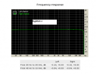
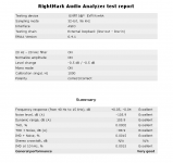
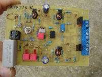
Kypton V
kypton v
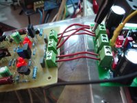
+/-50v
Idle current 60mA/pair
5 pairs njw0281,0302
All this test on a real speaker.
Last photo my sound card loop in out for comparision
kypton v
+/-50v
Idle current 60mA/pair
5 pairs njw0281,0302
All this test on a real speaker.
Last photo my sound card loop in out for comparision
Attachments


Last edited:
Kypton v
Using other software
Please on pictures 1&2 see the left channel where amplifier is connected(mono)
Using other software
Please on pictures 1&2 see the left channel where amplifier is connected(mono)
Attachments
Last edited:
Kypton v
Sorry guys the last picture in post #9043 isn't from Kypton V and it's too late for edit v.
Here is the correct one.
Sorry guys the last picture in post #9043 isn't from Kypton V and it's too late for edit v.
Here is the correct one.
Attachments
Last edited:
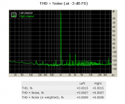
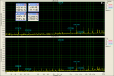
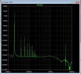
That is real good performance.
Strange how the distortion profile (dominant 3'rd) is also reflected
by the LT simulation. (below)
The sim and the real amp are right on.
I also got @ .0015% on LT at 1-10Khz.
Edit - I also got nearly equal H2/3 at 1K ... THD was around .001% there.
That is K-V2 , right ?
OS
Strange how the distortion profile (dominant 3'rd) is also reflected
by the LT simulation. (below)
The sim and the real amp are right on.
I also got @ .0015% on LT at 1-10Khz.
Edit - I also got nearly equal H2/3 at 1K ... THD was around .001% there.
That is K-V2 , right ?
OS
Attachments
Last edited:
I'm afraid that is ver.1 ,look at the picture.That is real good performance.
Strange how the distortion profile (dominant 3'rd) is also reflected
by the LT simulation. (below)
The sim and the real amp are right on.
I also got @ .0015% on LT at 1-10Khz.
Edit - I also got nearly equal H2/3 at 1K ... THD was around .001% there.
That is K-V2 , right ?
OS
Attachments
No , V2 has the super-pair left out .
So , you used a V1 PCB to make a V2.
Still , one excellent 1970's Japanese input stage. 🙂
PS - yours outperforms the Japanese ones by many magnitudes.
OS
So , you used a V1 PCB to make a V2.
Still , one excellent 1970's Japanese input stage. 🙂
PS - yours outperforms the Japanese ones by many magnitudes.
OS
Thanks Pete, this time is the Kypton ND under test.No , V2 has the super-pair left out .
So , you used a V1 PCB to make a V2.
Still , one excellent 1970's Japanese input stage. 🙂
PS - yours outperforms the Japanese ones by many magnitudes.
OS
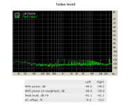
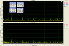
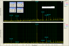
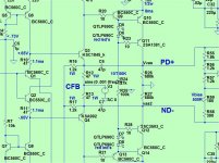
Here we have interesting things to look at.
I will post 3 different way for input gnd connection.
In the first picture the G2(GND) point connected at G1 point on the power amplifier board ,near +v/-v.The worst way!
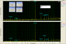
In the second picture this G2 (GND)point connected direct on star gnd.Better
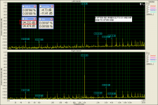
The other picture is what you see in the last picture,G2 connected to G1 point and the gnd from the IPS lifted from G2 and connected on star gnd directly.The best way.
Attachments
Last edited:
Ahh , interesting effect.
K-ND input pair virtual ground is the servo output (very good PSSR) ... not
earth.
That leaves the current feedback ground. Having that modulated by the speaker
return and OPS decoupling returns must degrade performance.
This is nowhere as pronounced with most VFA's , as their NFB returns are
not ground referenced.
We are still learning 😀 ....
PS - have you tried connecting speaker returns directly to the PS star ?? (another workaround).
OS
Last edited:
have you tried connecting speaker returns directly to the PS star ?? (another workaround).Ahh , interesting effect.
K-ND input pair virtual ground is the servo output (very good PSSR) ... not
earth.
That leaves the current feedback ground. Having that modulated by the speaker
return and OPS decoupling returns must degrade performance.
This is nowhere as pronounced with most VFA's , as their NFB returns are
not ground referenced.
We are still learning 😀 ....
PS - have you tried connecting speaker returns directly to the PS star ?? (another workaround).
OS
This is what i do always.🙂
have you tried connecting speaker returns directly to the PS star ?? (another workaround).
This is what i do always.🙂
Could you also try measure with speaker return connected to G2?
Thx
Could you also try measure with speaker return connected to G2?
Thx
Propably you mean to G1 the point where p.s 0v connected on the power amplifier board?
Propably you mean to G1 the point where p.s 0v connected on the power amplifier board?
Yes please i would like to see a worst case example☺
I will take care for this😀Yes please i would like to see a worst case example☺
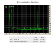
Here is what I did (below).
Injecting both a fixed ripple and / or a phased output signal (more realistic)
will degrade a CFA's feedback signal.
I guess this is another deficiency of current feedback topology.
I also did this to the K-ND servo ground reference , here no degradation. The servo's PSRR "swallow's" it up nicely.
The new Groner TIS (SG-1) is immune to a noisy ground , and most of the
VFA slewmaster IPS's negotiate even a nearly faulty ground reference
without any penalty. Most of those VFA IPS's lost about <5ppm , even
with 1V ripple on any earth reference.
So , be VERY anal with a CFA grounding.
Edit - CFA IPS's like the VSSA/CFA-X have a capacitive coupling to ground
.... they also seem less affected by a "dirty" ground (in simulation).
OS
Attachments
have you tried connecting speaker returns directly to the PS star ?? (another workaround).
This is what i do always.🙂

Attachments
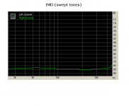
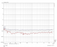
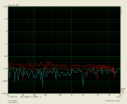
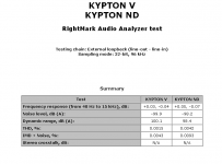
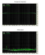
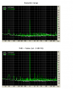
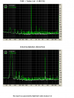
Kypton Nd vs Kypton V
Comparision
Comparision
Attachments
Last edited:
Comparision
what is the input impedance of Kypton V? with 22k resistor at the input the first resistor which connects at the input to the ground. With the following procedure I got about 22k as input impedance.
After the coupling cap, find the first resistor to ground... that is close enough.
OR:
Put a 50 - 100 K rheostat (pot) in series with your sound card and the amp (pos lead)
Power up the amp and apply a sine wave... 500 - 1000 Hz, 2.5 V ACrms
Adjust the pot until the ACrms across the pot and across the amp input are equal.
Power down, disconnect, and measure your pot value; that is your Zin.
Did u measure the input impedance of the Kypton V?
Look at post#5282,83,84 ,you will see all the details about Kypton V.what is the input impedance of Kypton V? with 22k resistor at the input the first resistor which connects at the input to the ground. With the following procedure I got about 22k as input impedance.
After the coupling cap, find the first resistor to ground... that is close enough.
OR:
Put a 50 - 100 K rheostat (pot) in series with your sound card and the amp (pos lead)
Power up the amp and apply a sine wave... 500 - 1000 Hz, 2.5 V ACrms
Adjust the pot until the ACrms across the pot and across the amp input are equal.
Power down, disconnect, and measure your pot value; that is your Zin.
Did u measure the input impedance of the Kypton V?
There is not info on input impedance of the kypton V.Look at post#5282,83,84 ,you will see all the details about Kypton V.
But im surprised that the distortion in ND is more than in V.
- Home
- Amplifiers
- Solid State
- Slewmaster - CFA vs. VFA "Rumble"