...I'm very curious how these capacitors sound in V2:
2 PCS Sanyo OS CON SA 2200uF 6 3V Organic Semiconductive Capacitors ESR 15M? | eBay
These have very good reviews, and they are much cheaper (and smaller) than the "regular" Nichicon FGs. Using smds in all possible position you can easily build a 160W power amp with "shortest signal path ever".
Do try a couple pairs. You might like the sound. No SMD for me for the time being. 😀
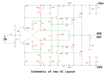
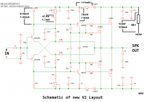
All in all it seems to be a new "Must-Build' PeeCeeBee was born.
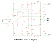
Two. The other one is the V1.1
🙂
"Ideally the feedback alone should have ultimate control over the sonics, not the devices." This is a very interesting question. It is certainly true however I'm very curious how these capacitors sound in V2:
2 PCS Sanyo OS CON SA 2200uF 6 3V Organic Semiconductive Capacitors ESR 15M? | eBay
OSCON has been for a long time my standard for feedback capacitors, whatever the amplifiers

Admittedly not read all 197 pages. Sorry if asking stupid question.
How to reduce the VAS current , say to 3 ma ? Any formula to calculate it?
Thanks in advance.
How to reduce the VAS current , say to 3 ma ? Any formula to calculate it?
Thanks in advance.
Another PeeCeeBee
Hi Shaan,
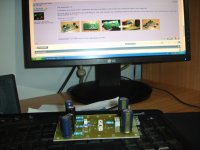
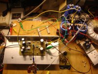
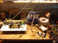
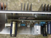
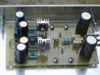
I built this PeeCeeBee V1.1. The PCB is adapted to fit on a drilled heatsink and for some existing components..
Super sound as expected! It runs with +-35V, 20k instead 15k for 70mA quiescent current. It is a nice compact modul. Offset can easily be set to 0V.
Thank you again for the beautiful amplifier.
Regards Olaf
Hi Shaan,
I built this PeeCeeBee V1.1. The PCB is adapted to fit on a drilled heatsink and for some existing components..
Super sound as expected! It runs with +-35V, 20k instead 15k for 70mA quiescent current. It is a nice compact modul. Offset can easily be set to 0V.
Thank you again for the beautiful amplifier.
Regards Olaf
Attachments
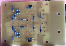
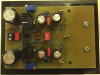
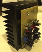
The PCB is adapted to fit on a drilled heatsink and for some existing components..
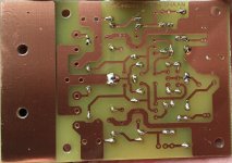
Looks like one of the FB cap shorted. Shaan's star grounding was good. People usually clear the copper around the holes for bolts so to avoid connecting the PCB ground to chasis in 2 points, or to avoid the connection at all (through that point).
Admittedly not read all 197 pages. Sorry if asking stupid question.
How to reduce the VAS current , say to 3 ma ? Any formula to calculate it?
Thanks in advance.
Hi Pwan. This is a very good question.
As this amplifier uses symmetrical VAS, quiescent current through the VAS devices depends largely on their DC current gain at the PS voltage it is running. In my experience an input-stage bias of between 1mA and 2mA will give you a VAS bias of between 5mA and 15mA, depending on VAS transistor hFE. The symmetrical VAS sometimes scares users as there is apparently no current limiting at the collector node. But in practice the transistors do not explode if small heat sinks are used and if the base current is limited, which we do limit by the 15K+1K current injectors at both sides, which also gives it some flexibility as we can select the effective resistance anywhere between 15K and 16K by turning the 1K trimmers.
Last edited:
Hi Shaan,
I built this PeeCeeBee V1.1. The PCB is adapted to fit on a drilled heatsink and for some existing components..
Super sound as expected! It runs with +-35V, 20k instead 15k for 70mA quiescent current. It is a nice compact modul. Offset can easily be set to 0V.
Thank you again for the beautiful amplifier.
Regards Olaf
Hi Olaf.

Great build!
I hope you corrected the copper trace short at the feedback node that Jay pointed out.
Sounds good? Well of course it does! It's a PeeCeeBee! 😎 😛 😀 😉
Cheers!
shaan
Hi Pwan. This is a very good question.
As this amplifier uses symmetrical VAS, quiescent current through the VAS devices depends largely on their DC current gain at the PS voltage it is running. In my experience an input-stage bias of between 1mA and 2mA will give you a VAS bias of between 5mA and 15mA, depending on VAS transistor hFE. The symmetrical VAS sometimes scares users as there is apparently no current limiting at the collector node. But in practice the transistors do not explode if small heat sinks are used and if the base current is limited, which we do limit by the 15K+1K current injectors at both sides, which also gives it some flexibility as we can select the effective resistance anywhere between 15K and 16K by turning the 1K trimmers.
I got it. Thanks much Shaan!
Hi all,Hi Olaf.
Great build!
I hope you corrected the copper trace short at the feedback node that Jay pointed out.
Sounds good? Well of course it does! It's a PeeCeeBee! 😎 😛 😀 😉
Cheers!
shaan
yes, the short I have corrected during assembly.
And exactly - The sound is perfect because it is a PeeCeeBee

There is no problem with the grounding. The amplifier is dead silent.
Regards Olaf
Hi Thimios ,
thanks for the feedback, how peeceebee compares with other best amplifiers you have made or heard , just out of curiosity as i have do not have that privilege , and looking forward to terrys opinion too as he done most best amp here and reading all his posting he is subjectively very objective
Sorry I am quoting a post directed to someone else. But I have something interesting to share. 🙂
A few days ago I took my stereo system based on the old PeeCeeBee V1 to a local friend's home and had a few hours of listening with various music tracks and a few sonically-spectacular films like MMFR. His system is comprised of a Yamaha AS-500 and Polk TSx330T towers and signal comes from a Xonar internal soundcard.
After about an hour of listening to it the Yamaha was replaced with the DIY amp and more tracks started being added to the playlist.
From bass to extreme highs, there was a very noticeable improvement in sonics. At loud passages, the sound was still transparent and clean. Everything sounded much more balanced and natural. And lastly, at 40W max, the apparent loudness shocked us both.
Interestingly, after an hour of abuse (including clipping, of course), nothing exploded that day and right now the same amp is driving my small 4" cheap satellites with the usual grace and clarity. (TBH, I expected a bang as the amp wasn't tested into continuous high power levels for an hour, ever before) 😎
So that's it, Sonics of the 2013's V1 PeeCeeBee.
(Note - Subjective opinion in this post, digest with caution) 😀
cheers


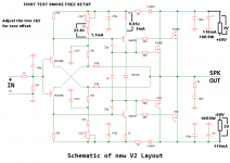

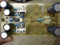
after 18R/5W removing.
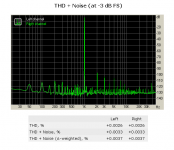
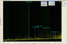
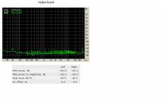
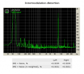
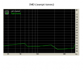
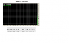
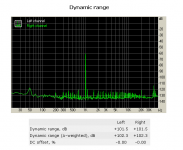
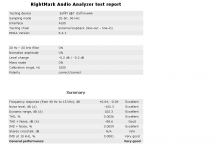
Here the measurements after 18R/5W removing.
The final test tomorrow.
How this play?
Fantastic!!!!!!!!!!!!As expected🙂
No one must lose this simple but no small amplifier,just my opinion.
Here the measurements after 18R/5W removing.
The final test tomorrow.
How this play?
Fantastic!!!!!!!!!!!!As expected🙂
No one must lose this simple but no small amplifier,just my opinion.
Attachments
Last edited:
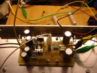
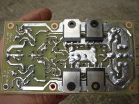
I haven't better way copper protection....this is a diy pcb.
That's some killer tinning!!!
BTW The first PeeCeeBee absolutely hum free! The separate inp GND connection do the job well.
I want to thank member <<coolwater>>,many of the parts on this the board is from his own donation🙂
Attachments
Last edited:
- Home
- Amplifiers
- Solid State
- PeeCeeBee