Ooh steel would be better to create a better field at the same time 🙂 just like in an AMT. but hell it stil looks good 🙂
ooh wow, where did you get 10x10x150 neo's 🙂
Bought one thousand from China.
1000 ??? wtf what where you planning! 150 meters of neo's... that would make 25 pairs of you ribbon ? 🙂 may i ask you how much they costed including shipping? i know bulk is the name of the game when you want something cheap. i bet taxes did not honored the 40 dollar value on the package 🙂 haha you might Pm me if you dont want to make that public for whatever reason 🙂 or dont want to share that at all of course 🙂
they do sound verry natural to me. since the membrane is pretty heavy it creates a nice balance. but light enough to extend to 20Khz. thats rare.
they do sound verry natural to me. since the membrane is pretty heavy it creates a nice balance. but light enough to extend to 20Khz. thats rare.
Last edited:
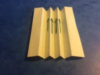
The planar is glued to the top of the N-S poles of magnets. It is better with out the nano iron when the magnetes is facing out. The planar 17 mm
wide and 150cm long.
By the way if you look at the front is right magnet facing north towards you and on the left south ? or other way around does not matter. or is left and right facing north towards you.
since if both where facing north or south towards you the thing would work like an amt and have harmonica side ways movement squeezing air out.
if left is north right is south like a normal ribbon, movement would be back and forth like a normal ribbon or cone loudspeaker.
1000 ??? wtf what where you planning! 150 meters of neo's... that would make 25 pairs of you ribbon ? 🙂 may i ask you how much they costed including shipping? i know bulk is the name of the game when you want something cheap. i bet taxes did not honored the 40 dollar value on the package 🙂 haha you might Pm me if you dont want to make that public for whatever reason 🙂 or dont want to share that at all of course 🙂
they do sound verry natural to me. since the membrane is pretty heavy it creates a nice balance. but light enough to extend to 20Khz. thats rare.
Hm I bougth them a long time ago think is was 3500 €. I wanted too make it commercial. Didnt work out, so now I just have some fun ;-).
Its made with ultra thin capacitor paper and 4 my alu. Its pretty light
Last edited:
By the way if you look at the front is right magnet facing north towards you and on the left south ? or other way around does not matter. or is left and right facing north towards you.
since if both where facing north or south towards you the thing would work like an amt and have harmonica side ways movement squeezing air out.
if left is north right is south like a normal ribbon, movement would be back and forth like a normal ribbon or cone loudspeaker.
Yes north and south is facing towards you. Correct it moves like a normal ribbon
aha weird i used the amt setup both of the same poles facing you. might need to try the normal method once, to see what happens. although i destroyed my membrane so have to make a new one, somewhere
The idea is that the planar is rigid vertically and can move horizontally. So the reverse of a normal ribbon tweeter. It may also be that this is one of advantages of an AMT
The idea is that the planar is rigid vertically and can move horizontally. So the reverse of a normal ribbon tweeter. It may also be that this is one of advantages of an AMT
yeah this all depends on the angle the thing is folded in, when the angle becomes smaller the horizontal plane wont be able to move back and forth, but will be able to move sideways. entering the AMT domain 🙂 at least thats my guess 🙂

Yes hopefolly 24db 250hz.And a 5-10db boost in the low end. A&E claims 93db 1 watt 🙂.
Mr ABJensen, respect!
A very interesting design, very well build but you got me confused.
You say that the magnets are like in a magnepan, so I wonder what magnepan exactly? The magnepan magnepan or the ribbon tweeter magnepan?
In the #33 pdf the picture is showing the magnets in a "ribbon" orientation not in a "magnepan" orientation, is this PDF drawing correct?
It isn't like you say in #48 with the north and south is facing towards you the drawing shows north and south - right and left!
How and where exactly are the conductors and how is it wired?
I definitely see a couple of advantages in this configuration and I am surprised -like some others here- how low it plays.
Personally I search for the best kind of planar ( ain't we all ) and several possibilities crossed my mind. ESL AMT Magnetostat and others like an AMT-like driver but ESL driven. Or an AMT-like driver with magnets between the folds.
Main objective is a "LOW" frequency driver that at covers the human voice part. Planars are superior here in my experience.
Then I like tho have sound pressure, unlike some I find dynamic range ( power ) an essential part of realism.
Oh what is an A&E dipole 18 ( post #52 )?
Edmund
@Edmund
You can see the 4 conductors in post 37.
This version has the magnets like the midrange woofer sektion in magnepan. See below.
Acoustic Elegance Dipole18 woofer for Open Baffle Apps
You can see the 4 conductors in post 37.
This version has the magnets like the midrange woofer sektion in magnepan. See below.
Acoustic Elegance Dipole18 woofer for Open Baffle Apps
Attachments
Hi ABJensen
Super interesting and very inspiring 🙂
I'm thinking whether it would make sense to only run the alu on the two mid folds leaving out the outmost, or make a fold more to act as the "suspension"?
I'm thinking that the outermost folds are very restricted in movement as one side is attached to the magnet.
Intuitively I would think it would make the movement of the "coil" more linear, and thereby decreasing THD ..... but on the other hand you would have two sides moving but not directly driven by the coil.
.... guess it should be easy to test, just disconnecting the two outermost tracks, measure and compare THD .....
I think it is a briliant concept ans it allows for large movement and it seales the sides, thereby both hlping for very low freq response. Cool 🙂
On the other hand I think the folds here will have a slightly more complex movement pattern (not just back and forth) because of the folds hinging together and making some sideways and twisting motions too. This compared to a normal ribbon, moving very much only back and forth, or for AMT where the motion is highly "sideways, because of their more flexible hinges taking "making up" for the movements.
How do you handle 4mu alu?? Cutting and gluing? .... and where do you get such thin material? (are both paper and alu from a large paper capacitor?
Cool work 🙂
Attachments
Hi ABJensen
Super interesting and very inspiring 🙂
I'm thinking whether it would make sense to only run the alu on the two mid folds leaving out the outmost, or make a fold more to act as the "suspension"?
I'm thinking that the outermost folds are very restricted in movement as one side is attached to the magnet.
Intuitively I would think it would make the movement of the "coil" more linear, and thereby decreasing THD ..... but on the other hand you would have two sides moving but not directly driven by the coil.
.... guess it should be easy to test, just disconnecting the two outermost tracks, measure and compare THD .....
I think it is a briliant concept ans it allows for large movement and it seales the sides, thereby both hlping for very low freq response. Cool 🙂
On the other hand I think the folds here will have a slightly more complex movement pattern (not just back and forth) because of the folds hinging together and making some sideways and twisting motions too. This compared to a normal ribbon, moving very much only back and forth, or for AMT where the motion is highly "sideways, because of their more flexible hinges taking "making up" for the movements.
How do you handle 4mu alu?? Cutting and gluing? .... and where do you get such thin material? (are both paper and alu from a large paper capacitor?
Cool work 🙂
I made a planar like that some 10 years ago. I just didnt realize just how good they were 🙂.You could place the first fold with out conductor closer to the center of the magnet. So you don´t lose sensivity.
4 my alu, use water and glass 🙂.I got it from a now closed capacitor factory sorry. Use ordinary alu from Irma (danish shop :-( ). and eks toiletpaper no joke.
- Status
- Not open for further replies.
- Home
- Loudspeakers
- Planars & Exotics
- Magnetic paper ribbon