It is the thick alu tape at the end that helps to hold the shape. If it in´t sloppy, it will straighten out if you go low. because of this there is not alu in the middle of the folds
Last edited:
well i give it another shot tomorrow, i also looked at some magnet structures in femm. my magnets are not ideal of course since i dont use the complete 20mm deep gap. i better should use 10x10 or something. a return path at the back should help the field even more. but it might be in the way and give weird resonances so wont be trying this soon 🙂
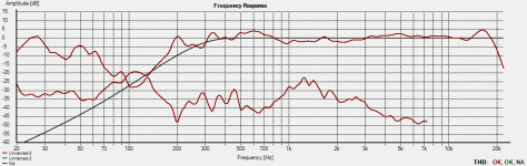
Ok i tried the W so 4 folds. different sizes result is a bit sad 🙁 loads of distortion and low ouput. i then tried te amt way with the same magnets just flipped them 90 degrees. made a 10 fold version instead of the 6 and 4 of the normal ribbon style magnet arrangement. SPL rocketed 12 db above the others. for the same given load. im not 100 convinced yet, but it looks this a more effective way. but it also decreases the low end conditions. i will try some different materials now to see if i can extend it a bit.
Interesting stuff.
WrineX, do you have a detailed picture of your setup with the direction of the conductors?
ATM and ribbon configuration have a different direction of the current.
WrineX, do you have a detailed picture of your setup with the direction of the conductors?
ATM and ribbon configuration have a different direction of the current.
Ok i tried the W so 4 folds. different sizes result is a bit sad 🙁 loads of distortion and low ouput. i then tried te amt way with the same magnets just flipped them 90 degrees. made a 10 fold version instead of the 6 and 4 of the normal ribbon style magnet arrangement. SPL rocketed 12 db above the others. for the same given load. im not 100 convinced yet, but it looks this a more effective way. but it also decreases the low end conditions. i will try some different materials now to see if i can extend it a bit.
Can you post measurements, so I can compare 🙂

Ok i tried the W so 4 folds. different sizes result is a bit sad 🙁 loads of distortion and low ouput. i then tried te amt way with the same magnets just flipped them 90 degrees. made a 10 fold version instead of the 6 and 4 of the normal ribbon style magnet arrangement. SPL rocketed 12 db above the others. for the same given load. im not 100 convinced yet, but it looks this a more effective way. but it also decreases the low end conditions. i will try some different materials now to see if i can extend it a bit.
Maybe like this
Attachments
i used it as this
N\/\/\/\/\/\/N
- .............. -
S...............S
Ofcourse my current did not go one direction but every pleat/fold it switched from down to up
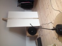
i used 4 x 40x20x5 mm magnets, not the biggest 🙂
your design is
N|S/\/\/\N|S like a normal ribbon
this first one has side ways movement. i did measure all failures be it not well documented. but the amt was by far the most efficient. (be it verry low resistance, but the others had that to 🙂)
i will upload some
N\/\/\/\/\/\/N
- .............. -
S...............S
Ofcourse my current did not go one direction but every pleat/fold it switched from down to up
i used 4 x 40x20x5 mm magnets, not the biggest 🙂
your design is
N|S/\/\/\N|S like a normal ribbon
this first one has side ways movement. i did measure all failures be it not well documented. but the amt was by far the most efficient. (be it verry low resistance, but the others had that to 🙂)
i will upload some
Last edited:
yout high ferquncy extend would be better since the foulds are not that deep. and the low and will be more since you got 1.5 meters of it 🙂 i only have 8 cm 🙂
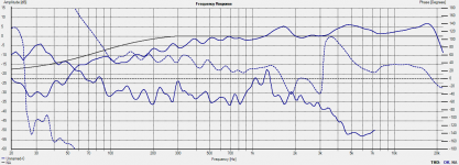
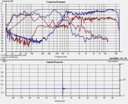
Here's a measurement. with a 16 folds membrane. but thats it the limit for the 30 mm gap, or have to find some reinforcement without Upping the resonance freq.
BLUE AMT STYLE
RED W style in normal ribbon magnet structure.
both measured at same distance around 25 cm, and resistance is almost the same. 2 Ohms so very low but good enough for testing. both there distortion is a tad to high for my taste but i think there is a margin to gain lower distortion. for instance my magnets also influence the pieces where the tracks go sideways, this will result in upward movement. not something you want 🙂 but since this one is so small 2 cm of the total 10 cm high has these sideways tracks. so have to make a bigger membranous and dont drive it the full length. (at least thats my theory)
and i have some hearable resonances left, witch i should be hunting down so i know what to do with it next time
i am very pleased the thing extends to 20khz. something i was afraid of with the deep folds
Attachments
Last edited:
- Status
- Not open for further replies.
- Home
- Loudspeakers
- Planars & Exotics
- Magnetic paper ribbon