Sound reduction by a Helmholtz resonator
Experimental results with adjustable resonators to dampen the tone produced* showed that the amplitude of the tone ... (frequency) could be decreased ~30 dB (or more).
*Adapted from Koopman and Neise (1980, 1982), study working with noise, attenuation, from blade passage of centrifugal fans
This very much relates to the picture showed above (post #13)
The resonant frequency is controlled by altering the dimension of the Helmholtz resonator, such as the length of the neck or the volume of the cavity of the resonator, or both of these. f = S/VL, 🙂simplified🙂 S area of port, V volume and L length of port.
Myonghyon Han, 2008
And as follows:
""...the Helmholtz resonator is employed to attenuate the oscillation characteristics of a deep cavtty duct, i.e., a side branch. The Helmholtz resonator is attached to the side of the duct.""
According to his linked in page the patent was granted in 1998 and on another part of the page granted in 1993. Then lower down he talks about the bass in the Dundee
"Our patented Acoustic Induction system with it 36db low-pass filter effect centered on 100hz feeds a 7ft long 1/4 wave transmission line"
He also talks about acoustic induction working with the standing waves within the enclosure.
Whatever he's doing sounds interesting and I'd like find out more
Mark
Attachments
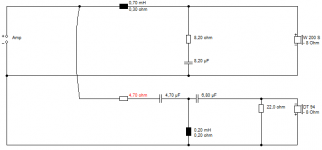
This is trivial to model in Akabak, and I have used HR's before to shape the response. This looks more like an extended vent reflex rather than a TL.
https://www.asa.org.uk/Rulings/Adjudications/2012/1/Alacrity-Audio/SHP_ADJ_176028.aspx
They say the patent expired over 10 years ago (the ruling was in 2011). UK patents last 15 years? Then you'd need to search pre 1986
dave
Thanks Dave, a very interesting link!
After all the guy seemingly had a unit of measurement named after him, at least according to himself:
"However, as the internal pressures cannot equalize in time (requires 5 to 10 % of a second, which reflects the value of acoustic inductance measured in Carrolls), the acoustic potential remains integrated with the applied signal with a small phase shift..."
(from the AA site)
Acoustic inductance, also known as inertance or acoustic mass, is measured in mks units of kg / (m ^ 4). There is no such unit as a Carroll 🙂.
The acoustical analogue of an electrical inductor coil is a rigid-walled tube open at both ends that is short enough so that the air in it moves as a whole without appreciable compression.
Acoustic inductance, also known as inertance or acoustic mass, is measured in mks units of kg / (m ^ 4). There is no such unit as a Carroll 🙂.
The acoustical analogue of an electrical inductor coil is a rigid-walled tube open at both ends that is short enough so that the air in it moves as a whole without appreciable compression...
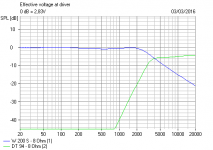
...below it's resonant frequency. Above that frequency, the resistance changes dramatically. In their standmounts, that frequency is 100Hz. In their floorstanders, it looks more like 200Hz.
What you described above is more like an acoustic conductor (or perhaps, a low-value acoustic resistor)
cw
Last edited:
Sound reduction by a Helmholtz resonator
Experimental results with adjustable resonators to dampen the tone produced* showed that the amplitude of the tone ... (frequency) could be decreased ~30 dB (or more).
*Adapted from Koopman and Neise (1980, 1982), study working with noise, attenuation, from blade passage of centrifugal fans
This very much relates to the picture showed above (post #13)
The resonant frequency is controlled by altering the dimension of the Helmholtz resonator, such as the length of the neck or the volume of the cavity of the resonator, or both of these. f = S/VL, 🙂simplified🙂 S area of port, V volume and L length of port.
Myonghyon Han, 2008
And as follows:
""...the Helmholtz resonator is employed to attenuate the oscillation characteristics of a deep cavtty duct, i.e., a side branch. The Helmholtz resonator is attached to the side of the duct.""
Yes, I heard them describe it as a "wide-band Helmholtz resonator" but imagine it on a much smaller scale, within their special stuffing (which is what their patent seems to be all about).
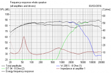
They reckon they get a roll-off of up to 36dB (as opposed to the 30dB quoted above), visible on their impedance plots.
And have you seen the rest of their impedance plots? That's some of the weirdest readings I've ever seen.
cw
copperweed why do you keep referring to Alacrity Audio as 'they' when this is your public profile?
About copperweed
Biography
Um, na!
Location
Brighton, UK
Interests
Intervention theory
Occupation
MD/Designer, Alacrity Audio
Country
United Kingdom
Real Name
Alacrity Jon
About copperweed
Biography
Um, na!
Location
Brighton, UK
Interests
Intervention theory
Occupation
MD/Designer, Alacrity Audio
Country
United Kingdom
Real Name
Alacrity Jon
Last edited:
Hi Jonathan,...
And have you seen the rest of their impedance plots? That's some of the weirdest readings I've ever seen.
cw
I will check them again.
Really nice speakers. 🙂
Can you link to the patent(s) we are referring to in this post
Can you disclose something about the nicest driver (?) of the Dundee-5
Also I asked the vendor about the front damping panel of the Dundee's, at the PT AudioShow-2016 in Lisbon, last weekend and I was told you can place it anywhere!!!... Would you clarify if that's for the standing waves formed/reflected by the interaction of room/speaker/floor. 😀
I'm a bit mystified what acoustic induction bass loading might be, or why I should care.
But Jon at Alacrity Audio is certainly someone I can relate to.
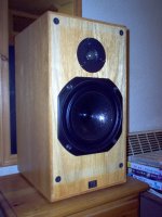
[Review] Alacrity Audio Caterthuns 8 - loudspeakers - [English]
These Caterthuns 8's are the sort of thing I like messing with myself. It's one of the better 2 ways IMO. BW3 seems to work best. 🙂
But Jon at Alacrity Audio is certainly someone I can relate to.
[Review] Alacrity Audio Caterthuns 8 - loudspeakers - [English]
These Caterthuns 8's are the sort of thing I like messing with myself. It's one of the better 2 ways IMO. BW3 seems to work best. 🙂
Attachments

I was rereading the review of the Cathertuns 8. It becomes clear to me that this is a low bafflestep design, best placed close to a wall. No soggy bass with boom there.
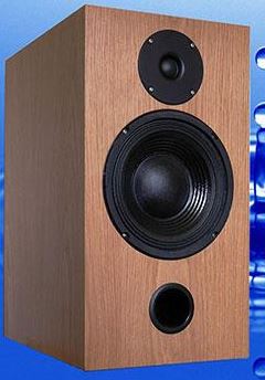
It's something I like myself. It's reflex, of course. But there is a trick with an elongated port (tuned lower) with reflex that it gets closer to 12dB/octave closed box.
My own take on the Cathertuns 8 is a lively efficient Sony bass with small bass coil. We have to take a beating on power droop at crossover, it's just how it works. But BW3 gives more power and less drop-out off-axis.
Very nice flattish impedance and near 90dB efficiency. Joe Rasmussen would approve. 🙂
Attachments
Last edited:
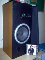
30 some years ago I briefly had the taller Clement's Phase Research with 8" woofer and 1.375" Audax dome mounted in a separate cabinet on top - - here's a cutaway of a smaller model - btw - what good can one reap from the H-Pas?

Last edited:
copperweed why do you keep referring to Alacrity Audio as 'they' when this is your public profile?
About copperweed
Biography
Um, na!
Location
Brighton, UK
Interests
Intervention theory
Occupation
MD/Designer, Alacrity Audio
Country
United Kingdom
Real Name
Alacrity Jon
😉
Busted!
But I only found out about this thread because my AA site hits went up by an order of magnitude.
Yeah, things are taking-off for me; they really do sound special.
The patent was granted. The speakers really do produce standing waves at every frequency from the point of the bass-unit.
My special filling holds and contains midrange frequencies, but can be tuned to release bass frequencies. That's why there's no foam bung at the exit of my TLs; my midrange-filtering is done before the energy is fed into the TL, resulting in better dynamics and bass amplitude.
It also flattens the impedance curves, giving the amp a smoother load which can only help the replay.
Glad you enjoyed them.
Working on the next model as we speak.
cw AKA AlacrityJon.
Hi Jonathan,
I will check them again.
Really nice speakers. 🙂
Can you link to the patent(s) we are referring to in this post
Can you disclose something about the nicest driver (?) of the Dundee-5
Also I asked the vendor about the front damping panel of the Dundee's, at the PT AudioShow-2016 in Lisbon, last weekend and I was told you can place it anywhere!!!... Would you clarify if that's for the standing waves formed/reflected by the interaction of room/speaker/floor. 😀
Hi Inductor
I think the guy only had a 30W amplifier at the show. I do shows with amps of that power, but at home I'm using a stereo classD 160W/ch monster that I'm about to double for passive bi-amping. It's smaller than my PPX900, but sounds better with no fan noise.
And I'm very careful with neighbours... 😀
With all due respect, my patent being expired gives me greater protection than it did when it was a-'live'. I was very young and naive when I conceived them, and little-to-no idea what I'd uncovered at first. In fact, it was Robin Marshall (while working at Mission) who defined it for me. On hearing my description of how they seemed to work, he turned to Henri and said "OMG, he's invented an Acoustic Inductor!!!" and then they tried to offer me a lot of money for my WWPatent Rights.
However, it all fell apart when I got ill with MS and I landed in hospital for a year. After that, people just thought I was crazy. It's taken me 20 years to rebuild it to where I was. So, thank you. I'm glad you enjoyed them.
There is an explanation of the pyramids on my site, but I can confirm that it is used to dissipate the Incidental Wave formed across the front baffle. When removed, the sharp edges of the recess perform 90% of the same function. Pushing the Incidental Waves off my baffles is the reason I have non-rounded edges on my speakers.
Jon Myles at HiFiWorld said the Dundee5s (and the same is true of the Dundee6s) were unaffected by room placement. Because they're putting out a standing wave at all times, the standing wave of the room (or 'room-nodes') is unnoticeable. The Caterthuns are less immune to placement, but both Cat6s and Cat8s can still cast a wonderful stereo image when close to their rear wall.
I import all my bass-units from the far-east. The only thing they have in common (apart from I insist on 8 ohm drives) is they have the most massive magnet possible for their chassis size, massive power capacity, and a low-compliance suspension (to suit my low-compliance Acoustic Induction system.
Did my own cross-over, and I use a similar topology across the ranges. This includes cross-inductance counter-measures, as all my speakers are so revealing that I can tell how close the cross-over components are to each other.
I can also hear the difference in bi-wired and mono-wired on them.
...below it's resonant frequency. Above that frequency, the resistance changes dramatically.
I said when the air moves as a whole without appreciable compression. I was talking about an ideal acoustical inductor, with acoustical reactance only.
Electrical inductive reactance = wL
Acoustical inductive reactance = wMa
Where:
w = 2 * Pi * f
L = electrical inductance in henrys
Ma= acoustical inductance in kg / (m ^ 4)
What you described above is more like an acoustic conductor (or perhaps, a low-value acoustic resistor)
In an acoustic conductor / waveguide / horn / transmission line / etc, the air does not move as an uncompressed mass.
An acoustic resistor would be a fine-mesh screen, capillary tube or such like, where dissipative losses occur due to viscous movement.
~~~~~~~~~~~~~~~~~~~~
It seemed to me that the Alacrity Audio website was implying that "acoustic induction" was something new and unique to them - to the extent that they had come up with the unit of "Carroll" to measure acoustic inductance (to be correct it should be carroll with a lowercase "c").
I was simply trying to point out that like most things in acoustics, acoustical induction / inductance / inertance is nothing new 🙂.
I said when the air moves as a whole without appreciable compression. I was talking about an ideal acoustical inductor, with acoustical reactance only.
Electrical inductive reactance = wL
Acoustical inductive reactance = wMa
Where:
w = 2 * Pi * f
L = electrical inductance in henrys
Ma= acoustical inductance in kg / (m ^ 4)
In an acoustic conductor / waveguide / horn / transmission line / etc, the air does not move as an uncompressed mass.
An acoustic resistor would be a fine-mesh screen, capillary tube or such like, where dissipative losses occur due to viscous movement.
~~~~~~~~~~~~~~~~~~~~
It seemed to me that the Alacrity Audio website was implying that "acoustic induction" was something new and unique to them - to the extent that they had come up with the unit of "Carroll" to measure acoustic inductance (to be correct it should be carroll with a lowercase "c").
I was simply trying to point out that like most things in acoustics, acoustical induction / inductance / inertance is nothing new 🙂.
This is where our theories depart.
As my true Acoustic Inductor produces an acoustic back-EMF (otherwise known as a Standing-Wave) at all frequencies below 10KHz (as tested so far, I intend to take it higher this year; Full-Range) THE AIR MASS DOES NOT MOVE as the cabinet air-load solidifies and prevents the drive unit from moving, but strangely it gets very loud in the process. That is because the drive-unit is coupled more efficiently to the air load (movement of the cone is the same as an electric motor 'slipping')
Have you seen a Newton's Craddle when the outer weights swing?
That is 'air-mass movement' in this analogy.
When the moving weight strikes the stationary weight, the energy is INSTANTANEOUSLY transmitted through to the furthermost weight, which leaps into the air with the same given time-period as the first weight.
It's that moment of instantaneous energy transference through a non-compressible medium I exploit with my designs.
Watch my bass-units; they hardly ever move, even under the harshest conditions. That's what gives them their unique power-handling charateristics and dynamic range.
At resonant frequencies (ie, cabinet standing-wave frequencies) the air in the cabinet becomes an UNCOMPRESSABLE LOAD, just at that frequency while still being compressed by other frequencies at the same time, resulting in box-honk and bass-rolloff.
My cabinets are in that condition ALL THE TIME, consistently, AT EVERY FREQUENCY up to 10 K Hz (as tested so far), meaning there is no box-honk and no bass-rolloff from them.
It really is new.
cw
I'm sometimes disappointed with my colleagues' reaction to new ideas. "Crappy" is just not in my vocabulary, it's all about the science and maths. 😱
As an old hand at speakers, I have studied all the theories of diffraction and bass loading. TBH, I think you trade off one thing against another.
What is better, closed box, reflex, transmission lines or aperiodic? I don't expect Jon Carroll to give away hard-won ideas for nothing. Joe Rasmussen ran into some severely insulting behaviour for suggesting that flat impedance was a good thing. Even extending to the bass Fs.
If Jon Carroll has found a way to mechanically equalise the bass (approx 50Hz) Fs peak, I consider it realistic. I'm forever moving damping materials around cabinets to get it just right. 🙂
Joe Rasmussen ran into some severely insulting behaviour for suggesting that flat impedance was a good thing. Even extending to the bass Fs.
Seriously?! Best bass ever and what a proper compression bass horn or TL provides and one reason why the BIB pipe horn performs so well overall.
GM
Watch my bass-units; they hardly ever move, even under the harshest conditions. That's what gives them their unique power-handling charateristics and dynamic range.
My cabinets are in that condition ALL THE TIME, consistently, AT EVERY FREQUENCY up to 10 K Hz (as tested so far), meaning there is no box-honk and no bass-rolloff from them.
It really is new.
Sounds almost too good to be true 🙂.
What stops other speaker manufacturers from adopting your Acoustic Inductor technique, now that the patent has expired?
Looks more like fun pseudoscience to me. The author is engaging in discussion which is rather rare perhaps because there is no such thing as bad publicity when it comes to this sort of thing and possibly to work on what lines might work. So why not join in and see if you can get him to make a comprehensible statement that is wrong rather than letting him get away with technical sounding statements that cannot be pinned on something real.It really is a new example of very crappy pseudoscience.
- Status
- Not open for further replies.
- Home
- Loudspeakers
- Multi-Way
- What is "Acoustic Induction" by designer Jon Carroll