Thanks! 🙂
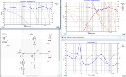
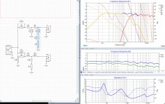
I implemented the tweeter and woofer circuit but i had to invert the tweeter to get any kind of phase alignment.
Here is the result completely unchanged apart form the inverted tweeter:

Tweeter correct direction:

Is this in the ballpark of what you expected? 🙂
I implemented the tweeter and woofer circuit but i had to invert the tweeter to get any kind of phase alignment.
Here is the result completely unchanged apart form the inverted tweeter:
Tweeter correct direction:
Is this in the ballpark of what you expected? 🙂
Attachments
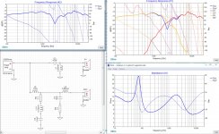
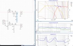
Okey, yet another design. This is based on the Woofer circuit system7 posted above and the tweeter circuit used before.
The FR is aligning rather well with erics house curve making the tweeter a little less "bright". The phase alignment is decent and the impedance is never lower than 4ohm.
Thoughts? 🙂

Inverted tweeter:

The FR is aligning rather well with erics house curve making the tweeter a little less "bright". The phase alignment is decent and the impedance is never lower than 4ohm.
Thoughts? 🙂
Inverted tweeter:
Attachments
I think you are getting very very close. 🙂 I would try to increase L5 to get a smoother transition between the woofer and tweeter, but I think it's very good right now. The simpler schematic will also hopefully be cheaper. 🙂
What is C4/R4 doing? If it's a Zobel, it should be closer to the woofer. This should improve your impedance overall.
You are at the point right now where you should consider listening to your design. My own preferences not withstanding, you would develop your own "ear" a lot better by making this and then changing anything your ear doesn't like.
Best,
Erik
I like that you like it! 😀I think you are getting very very close. I would try to increase L5 to get a smoother transition between the woofer and tweeter, but I think it's very good right now. The simpler schematic will also hopefully be cheaper.
What is C4/R4 doing? If it's a Zobel, it should be closer to the woofer. This should improve your impedance overall.
You are at the point right now where you should consider listening to your design. My own preferences not withstanding, you would develop your own "ear" a lot better by making this and then changing anything your ear doesn't like.
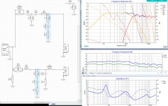
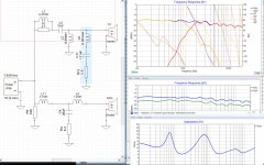
I have done a bit of work removing the notch in the woofer and R1 in the tweeter. As you say, simpler is cheaper and i guess its good to get rid of components thats not needed overall.
I tried to increase L5 but i didn't see much of an improvement so i left it for now 🙂
Im not sure what to call the C4/R4 network but it does some nice things, i get a really nasty dip at 4kHz if i remove it so id better let it be 😀
Its probably a good point to actually start buying the parts and building this now. I have a really convenient way of adjusting the tweeter level by tweeking R3 so ill probably buy a bunch of resistors to play with there 🙂 So next step may actually be to convert this into real life component values now? If there isn't any other issues that you can spot in the circuit.
Attachments
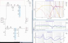
Check your impedance again. 🙂 Anything you can do to prevent that < 4 Ohm dip at 2kHz is going to be useful.
Best,
Erik
Best,
Erik
😀I like it! What happened to the notch filter you had in the bass?
I was able to replace the effects of it when i removed it. I didn't deliberately put it there in the first place like i did with the notch in the tweeter to eliminate a bump in the higer frequencies. I think it was placed there to correct some peek in in the woofer that i took the circuit from(the one system7 posted).
I don't really know what to do to raise that minimum impedance drop there, do you have any ideas? It would feel great if i could do it thoughCheck your impedance again. 🙂 Anything you can do to prevent that < 4 Ohm dip at 2kHz is going to be useful.
EDIT
Ill take that back! I managed to lower C2 alot and compensated that by increasing L2 and now look at it 🙂
Attachments
Last edited:
Much better. Do you really need C1 to be so large?
Since this is where you'll end up spending your money on good caps, lower is better (i.e. cheaper).
Only Solen/SCR/Axon to my knowledge have 7.5 uF caps. If you can use a 6.8 it gives you broader range of parts, otherwise you'll need a 6.8uF + 0.68uF
Since this is where you'll end up spending your money on good caps, lower is better (i.e. cheaper).
Only Solen/SCR/Axon to my knowledge have 7.5 uF caps. If you can use a 6.8 it gives you broader range of parts, otherwise you'll need a 6.8uF + 0.68uF
I don't really know what to do to raise that
minimum impedance drop there, do you have any ideas? It would feel great if i could do it though
EDIT
Ill take that back! I managed to lower C2 alot and compensated that by increasing L2 and now look at it 🙂

Okey, i killed C1 altogether instead 😉 Its really addictive getting the FR right and eliminating components! Now im down to:Much better. Do you really need C1 to be so large?
Since this is where you'll end up spending your money on good caps, lower is better (i.e. cheaper).
Only Solen/SCR/Axon to my knowledge have 7.5 uF caps. If you can use a 6.8 it gives you broader range of parts, otherwise you'll need a 6.8uF + 0.68uF
5 coils
3 caps
4 resistors
To be honest, i haven't started to try to map the components to real values yet 🙄
I know C4 is big but i have been trying to get it lower and still maintain the FR and phase alignment without success.
I should go for different coil types for tweeter and woofer right? Also, prefered caps, i think you mentioned it before but now when its only 3, maby step them up a little bit? 😛 I have no clue what each crossover will cost yet but what the heck.. 😀
Attachments
I think you killed one resistor too many. 🙂 The resistor across L11 was Baffle Step Compensation. Check your FR down to 20 Hz before removing that one! 🙂
Generally, coils in the tweeter can be thinner, and higher DCR types. In the tweeter filter you spend your money in the caps and resistors. In the woofer you spend it in coils, but given the relative age of the drivers, etc. it's not worth going crazy with parts. In the tweeter I'd go with Mundorf MKP's and Mills resistors. In the woofer any coil with relatively low resistance (~ 0.2 to 0.4 Ohms) will work. R5 is entirely optional.
Generally, coils in the tweeter can be thinner, and higher DCR types. In the tweeter filter you spend your money in the caps and resistors. In the woofer you spend it in coils, but given the relative age of the drivers, etc. it's not worth going crazy with parts. In the tweeter I'd go with Mundorf MKP's and Mills resistors. In the woofer any coil with relatively low resistance (~ 0.2 to 0.4 Ohms) will work. R5 is entirely optional.
Yea, i know it was baffle step compensation, but i didn't really see the point of it when i looked at the FR after removing it 🙂 The upside was that i got rid of one of the coils there apart from the resistor.I think you killed one resistor too many. 🙂 The resistor across L11 was Baffle Step Compensation. Check your FR down to 20 Hz before removing that one! 🙂
Look at this, maby im overlooking something:
Attachments

Hi Sultanen
I haven't posted for a while but I have been following the thread.
I have just modeled your last circuit and it looks good. I agree you don't need the baffle step correction you removed.
I have been playing around with your files using Passive Crossover Designer The woofer filter transfer function has a 6dB drop between 200Hz and 700 Hz which takes care of the baffle step.
I used a -2cm offset for the woofer (about 0.77inch). Are you still using this value?
Using this offset I found that the phase match improved when I changed C2 to 8.2uF and L2 to 0.33mH.
Looking good 🙂
Robert
Thanks 😀 I hope you have learned something from this thread aswell!Hi Sultanen
I haven't posted for a while but I have been following the thread.
I have just modeled your last circuit and it looks good. I agree you don't need the baffle step correction you removed.
I have been playing around with your files using Passive Crossover Designer The woofer filter transfer function has a 6dB drop between 200Hz and 700 Hz which takes care of the baffle step.
I used a -2cm offset for the woofer (about 0.77inch). Are you still using this value?
Using this offset I found that the phase match improved when I changed C2 to 8.2uF and L2 to 0.33mH.
Looking good 🙂
Robert
What network of components is the "woofer filter transfer function"? 🙂
Im using 1.32in delay now 🙂
Ill upload the XSim file here, dont forget to vertical center the FR to -30dB.
I understand that, thanks for the concern 🙂 But note something, iv'e learned enough to actually not make that misstake any longer 😉 😀Good deal. 🙂
I was just worried since I couldn't see the < 100 Hz.
Best,
Erik
Thanks for this, i will try to have it in mind when picking components 🙂 I will keep R5, it reminds me of your avatar somehow 😛Generally, coils in the tweeter can be thinner, and higher DCR types. In the tweeter filter you spend your money in the caps and resistors. In the woofer you spend it in coils, but given the relative age of the drivers, etc. it's not worth going crazy with parts. In the tweeter I'd go with Mundorf MKP's and Mills resistors. In the woofer any coil with relatively low resistance (~ 0.2 to 0.4 Ohms) will work. R5 is entirely optional.
If anyone of you has ideas for eliminating more parts don't be afraid to tell me 😛
Attachments
Last edited:
I noticed that Audiohobby does not sell Mills resistors i can only see Mundorf and Jantzen Resistors - Fidelity Components ShopGenerally, coils in the tweeter can be thinner, and higher DCR types. In the tweeter filter you spend your money in the caps and resistors. In the woofer you spend it in coils, but given the relative age of the drivers, etc. it's not worth going crazy with parts. In the tweeter I'd go with Mundorf MKP's and Mills resistors. In the woofer any coil with relatively low resistance (~ 0.2 to 0.4 Ohms) will work. R5 is entirely optional.
From what i can see http://www.audiohobby.eu/en/5531-jantzen-superes-resistors-10w is the middle alternative between the cheaper MOX resistors and http://www.audiohobby.eu/en/314-mundorf-m-resist-supreme
Last edited:
I noticed that Audiohobby does not sell Mills resistors i can only see Mundorf and Jantzen Resistors - Fidelity Components Shop
From what i can see Jantzen Superes resistors 10W - Fidelity Components Shop is the middle alternative between the cheaper MOX resistors and Mundorf M-Resist SUPREME - Fidelity Components Shop
Mundorf resistors are are used by many. Remember the age of these drivers and that this is a learning trip, not necessarily where you will end. 🙂 You definitely don't need to buy the most expensive parts.
Best,
Erik
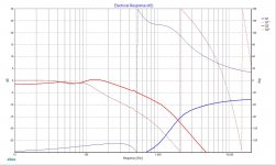
What network of components is the "woofer filter transfer function"?
The transfer function is effectively the electrical response of the crossover.
PCD shows this as one of its charts. I don't think XSim does this.
Here is the transfer function for your crossover.
Robert
Attachments
Sure XSim has this. Just select the "filter response (dB)" graph. Like the FR graph, when you select each driver you need to choose the phase plot.
An alternate view of the same information is the Voltage graph. The voltage graph is available for any component, not just speakers, but it's output is in Volts as opposed to relative dB.
Here's an example from a center channel I'm working on:

As you can see, the "transfer function" shows that the woofer's electrical input will be about -9.4 dB at 1kHz and about 120 degrees behind the input. If I compare the raw driver measurements, to the predicted output it is indeed about -9.4 dB at 1kHz. (XSim is exact, but I'm saying "about" 9.4 because I'm rounding).
Best,
Erik
An alternate view of the same information is the Voltage graph. The voltage graph is available for any component, not just speakers, but it's output is in Volts as opposed to relative dB.
Here's an example from a center channel I'm working on:
As you can see, the "transfer function" shows that the woofer's electrical input will be about -9.4 dB at 1kHz and about 120 degrees behind the input. If I compare the raw driver measurements, to the predicted output it is indeed about -9.4 dB at 1kHz. (XSim is exact, but I'm saying "about" 9.4 because I'm rounding).
Best,
Erik
Attachments
Last edited:
A "transfer function" is just a fancy way of saying "the math that explains the relationship of output vs. the input." Since it's a relative view (out vs. in), the graphs are normalized to 0 dB. This is different again from the Voltage graph which is based on the amplifier settings. As you vary the amplifier output (wattage) in XSim the V will go up and down, but the transfer function, since it's an explanation of relative differences, will not change.
Among other uses, it's great for checking that your high pass filter slopes actually meet specified safety requirements. That is, making sure the -3dB point and slope met manufacturer's guidelines to prevent a tweeter from blowing. Sultanen's tweeter is a bit of a tank, so it's not such a big deal. 🙂 Other tweets, especially epxensive ribbons, are more delicate.
Best,
Erik
Last edited:
- Status
- Not open for further replies.
- Home
- Loudspeakers
- Multi-Way
- 2 Way speakers - Suggestions on improvements?