Ever wonder what signal is coming from that second voice coil?
Got to admit this is the first dual voice coil driver I've ever had, Brutus BRZ15D4 (don't tell my audio friends I bought a car subwoofer).
After 50 years of experimenting with motional feedback on and off, thought I'd check out a DVC.
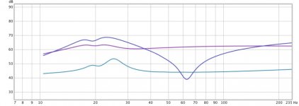
Below is the signal from the second voice coil in blue (with the big dip). The mostly straight curve is the signal in. The curve with the bump (for want of the nerve to call it an obvious anatomically derived term) at 25 Hz is the Fo straight out of the box measured with 100 Ohms in series (while sitting on a cardboard box and you can still smell the glue; rating is 21 Hz). Different absolute values for the curves but relative dB value for each curve alone is true.
Interesting?
Ben
(Just fooling around with available gear and lots of alligator clips while on vacation, but that's what is looks like.)
Got to admit this is the first dual voice coil driver I've ever had, Brutus BRZ15D4 (don't tell my audio friends I bought a car subwoofer).
After 50 years of experimenting with motional feedback on and off, thought I'd check out a DVC.
Below is the signal from the second voice coil in blue (with the big dip). The mostly straight curve is the signal in. The curve with the bump (for want of the nerve to call it an obvious anatomically derived term) at 25 Hz is the Fo straight out of the box measured with 100 Ohms in series (while sitting on a cardboard box and you can still smell the glue; rating is 21 Hz). Different absolute values for the curves but relative dB value for each curve alone is true.
Interesting?
Ben
(Just fooling around with available gear and lots of alligator clips while on vacation, but that's what is looks like.)
Attachments
Last edited:
The blue curve is related to cone velocity. Not something I instinctively knew, rather I had the benefit of Reading Jeff Macaulay's article in Electronics and Wireless World Feb' 1997. I also still have the subwoofer constructed according to the article. jeff macaulay's audio amp designs Have a look at the subwoofer tab.
Keith
Keith
Exactly!
Have you thought of building the Macaulay motional feedback amp?
My mantra is, "motional feedback, the last frontier". There's feedback everywhere else... except around the weakest link of all.
B.
Have you thought of building the Macaulay motional feedback amp?
My mantra is, "motional feedback, the last frontier". There's feedback everywhere else... except around the weakest link of all.
B.
Exactly!
Have you thought of building the Macaulay motional feedback amp?
B.
Perhaps I did not make myself clear. I built the whole project. Being a bit impatient I initially used an amplifier that was to hand using his "front end" The phase relationships in the loop are such that one might imagine there is a mistake when you see NFB being connected to an op amp non inverting input.
One very apparent limitation of the system is that it does not overload gracefully, probably explaining why proprietry systems often use some form of soft limiting of maximum excursion.
Keith
Forget DVC, Ben...
In the Netherlands are 2 sources supplying acceleration sensors in SMD that are to be mounted on the voicecoil-former, based on the original Philips MFB.
They are:
http://piratelogic.nl/?p=en.home
http://mfblabs.nl
In the Netherlands are 2 sources supplying acceleration sensors in SMD that are to be mounted on the voicecoil-former, based on the original Philips MFB.
They are:
http://piratelogic.nl/?p=en.home
http://mfblabs.nl
Last edited:
Gotta laugh. You are positively Canadian: instead of saying I'm a jerk for not reading your post carefully, you were polite!Perhaps I did not make myself clear. I built the whole project. Being a bit impatient I initially used an amplifier that was to hand using his "front end" The phase relationships in the loop are such that one might imagine there is a mistake when you see NFB being connected to an op amp non inverting input.
One very apparent limitation of the system is that it does not overload gracefully, probably explaining why proprietry systems often use some form of soft limiting of maximum excursion.
Keith
And, quite right about weird phases. I didn't check phases in my earlier MF work with a bridge sensor, but I did destroy a driver, apropos your final comment.
Which is why I'm feeling good about experimenting with the Brutus car-sound driver rated at 10,000 watts before the frame melts (OK, maybe just 1200 watts before the Nomex spider collapses... OK, I really don't believe those ratings, but pretty stratospheric versus an ordinary 100 watt amp).
The REW phase plot for the second VC ran plus and minus 120 degrees with a strange jump right at resonance (or which may be an artefact of how REW plots phase). Tricky to get enough feedback factor when the phases are so extreme. But I did run MF successfully for many years without a hitch by keeping the feedback factor low; which of course means low benefit.
Do you have measurements or observations of your results?
Ben
Last edited:
Do you have measurements or observations of your results?
Ben
No I have no acoustic measurements of the system, but I believe it pretty much replicated the author's original. My understanding of the relationship between loudspeakers and rooms has certainly advanced since 1997. It makes you wonder what is being achieved when room modes go to work on a woofer that is equalised to within a dB or so.
Currently I am into dipoles in the form of Linkwitz LX521's but have toyed with the idea of a double bass array approach to combatting room modes. Trouble is the dipoles need to be away from boundaries whereas the bass array is against the front and back walls.
Good to hear you Canadians are noted for your politeness!.
Keith
This concept really intrigues me. I do think that there may be some conceptual errors with this stuff, but I'll have to dig deeper..
Are the voice coils co-wound? In other words, are they one on top of the other?
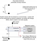
If so, they are coupled all to heck, and the signal of the second cannot be just the velocity component. It has to contain the information on rate of change of flux due to motion (velocity), drive rate of change of current, eddy current losses which readback as IR drop, as well as rate of change of the system inductance ( I dL/dt.)
I did some stuff for others a while back, and one of the things produced was a version of this pic. (SW, you'll recognize it)
Of note, the difference between coil voltages is actually just the IR drop of the driven coil. All system non linearities which attack the magnetic flux are coupled to both coils, and will not present within the difference signal. In addition, any energy which is used to perform work (what we hear), will present as a combo of real (resistive) and imaginary (energy storage) flux coupled to both coils. edit: an inductance meter will simply lump all reactive as part of the inductance reading, and all the in phase as the effective series resistance. I wonder what exactly can be done with the difference signal, which is only the effective drive coil resistance? Hmmm
I guess it would be great to compensate for the copper losses as the drive coil heats up, as well as the proximity loss changes with frequency and gap inductance changes.
I'll have to think a tad more as to whether or not the second coil's voltage is simply the velocity. The apps I derived this for assume the coils don't move, that scenario causes hundreds of millions of dollars worth of damage..frowned upon of course..but interesting for DVC's..
John
Are the voice coils co-wound? In other words, are they one on top of the other?
If so, they are coupled all to heck, and the signal of the second cannot be just the velocity component. It has to contain the information on rate of change of flux due to motion (velocity), drive rate of change of current, eddy current losses which readback as IR drop, as well as rate of change of the system inductance ( I dL/dt.)
I did some stuff for others a while back, and one of the things produced was a version of this pic. (SW, you'll recognize it)
Of note, the difference between coil voltages is actually just the IR drop of the driven coil. All system non linearities which attack the magnetic flux are coupled to both coils, and will not present within the difference signal. In addition, any energy which is used to perform work (what we hear), will present as a combo of real (resistive) and imaginary (energy storage) flux coupled to both coils. edit: an inductance meter will simply lump all reactive as part of the inductance reading, and all the in phase as the effective series resistance. I wonder what exactly can be done with the difference signal, which is only the effective drive coil resistance? Hmmm
I guess it would be great to compensate for the copper losses as the drive coil heats up, as well as the proximity loss changes with frequency and gap inductance changes.
I'll have to think a tad more as to whether or not the second coil's voltage is simply the velocity. The apps I derived this for assume the coils don't move, that scenario causes hundreds of millions of dollars worth of damage..frowned upon of course..but interesting for DVC's..
John
Attachments
Last edited:
This concept really intrigues me. I do think that there may be some conceptual errors with this stuff, but I'll have to dig deeper..
Are the voice coils co-wound? In other words, are they one on top of the other?
In most cases, one coil is wound onto the former first, and the second one is wound over the first one. Naturally, it is more expensive to wind and terminate dual voice coils, and you will typically pay a small premium compared to a similar single voice coil speaker.
My impression is these are to get 100's of Watts out of a 12V battery. I imagine not using one coil as drive derates the specifications? There is a lot of interest in this problem from, of all people, the desktop computer speaker manu's (the big ones).
Last edited:
My impression is these are to get 100's of Watts out of a 12V battery. I imagine not using one coil as drive derates the specifications? There is a lot of interest in this problem from, of all people, the desktop computer speaker manu's (the big ones).
I'd expect the transient dissipation would be roughly half. The long term dissipation would take a hit, but not half since the thermal flux path isn't changed that much, but inner vs outer would make a diff. But the R loss certainly doesn't change.
The OP seems to be looking at fidelity aspects though, not so much overall power.
John
Whatever the power de-rating from using just one of the coils, still should give me lots of headroom with a small amp.
A lot of the history of MF has to do with getting a gallon of sound out of a pint of speaker. In particular, (1) being able to shove the cone further below speaker resonance and (2) being able to contract cone motion at resonance. But for me, the goal is sound from a shaking-cardboard sub driver as clean as my shaking-SaranWrap ESLs.
The matter of direct inductance of voltage from one VC to the other VC would seriously compromise the use of a VC for MF. But the electric output of the sensor VC sure looks a lot different than the electric signal into the drive VC. Some drivers have the coils on opposite sides of the coil former - might help.
About room modes: it is the sim-lovers who need to lose sleep over room modes, not MF. Actually, an MF speaker in a corner might act as an active room mode equalizer. (Best feasible approach to mode modes is using carefully located (AKA tested) subs in greatest number around room that you and spouse can handle.)
Ben
Last edited:
I should probably stay shut up about this as I have only thought about the whole thing peripherally, but in the last 30 years or so since that first happened, accelerometers have developed drastically to the extent that they would certainly be my first step in designing a MF woofer system. Cheap, fast, light, linear. Probably smoke the doors off an old fashioned EM feedback plan.. 2 cents.
Forget DVC, Ben...
In the Netherlands are 2 sources supplying acceleration sensors in SMD that are to be mounted on the voicecoil-former, based on the original Philips MFB.
In earlier decades, I doubted you can use a 25-cent accelerometer to control an expensive driver. For Philips, you really can take a cheap driver in a small box and make it pretty nice with accelerometer MF. But that isn't my purpose. Granted, even a cheap accelerometer of a few decades ago is better than the 10% distortion and miserable transient behaviour of even high quality shaking-cardboard drivers.
Feedback is not a metaphysical concept; it is a matter of having phase right across the entire relevant passband. So can you take a signal from a pasted-on accelerometer and twin it to the clean signal from your pre-amp?
I'm sure somebody somewhere today is using quality accelerometers for quality MF. Who?
BTW, I'm just fooling around with DVC to see if it has advantages over using a bridge approach. I'll be posting sound tracings after my vacation.
Ben
Many thanks to jneutron for analysis. Mostly over my head, sadly. But to some extent the cross-coupling would get zero'd out when fed back?
A lot of that analysis would lead a builder to favour the bridge approach. In theory, the bridge balances those various factors - such as coil inductance and maybe even the factor so beloved on this forum, heat compression - and only the pure back-EMF remains. In practice, I got great results just doing resistive balancing, just guessing how far I could squeeze down to a pure signal and how much of that signal I could feed back.
Unless you use an external sensor, non-linearities of the magnet are a problem. But I suspect that in a quality driver, the magnet is a lot more linear than the piece of rubber holding the cone in place.
However, there is something of great practical importance in the analysis: velocity and acceleration which interact with cone size and everything else. MF (which deals with acceleration (or is it velocity)) destroys the artful way drivers fudge to produce kind of flat output by insisting that the cone has a motion corresponding to the signal from the pre-amp. So when you switch in MF, you need to EQ the pre-amp signal with the correct bass boost and slope.
Ben
Last edited:
Hey, Ben..In earlier decades, I doubted you can use a 25-cent accelerometer to control an expensive driver. For Philips, you really can take a cheap driver in a small box and make it pretty nice with accelerometer MF. But that isn't my purpose. Granted, even a cheap accelerometer of a few decades ago is better than the 10% distortion and miserable transient behaviour of even high quality shaking-cardboard drivers.
Feedback is not a metaphysical concept; it is a matter of having phase right across the entire relevant passband. So can you take a signal from a pasted-on accelerometer and twin it to the clean signal from your pre-amp?
I'm sure somebody somewhere today is using quality accelerometers for quality MF. Who?
BTW, I'm just fooling around with DVC to see if it has advantages over using a bridge approach. I'll be posting sound tracings after my vacation.
Ben
Well first on the accelerometers.. The old system has been abandoned, so no more in rubber suspended elements like in the old days.
Sure, they generate a certain amount of distortion, but adding a second transistor reduced that number by a factor of 10..
OK, you might not like the concept and want to try DVC. Problem with that system is not only temperature, but also stray magnetism emitted by the active VC, injected into the signal of the passive VC, preventing an accurate signal from the passive VC. I can imagine the effect to be frequency dependant, where you like to have a relative frequncy independant feedback signal...
Keep me posted, how you solve this problem 😉
I didn't reed all of the posts, but I think I found some old article detailing what you want to do: http://www.macaulayaudio.co.uk/roaring sub.pdf
I'm sure somebody somewhere today is using quality accelerometers for quality MF. Who?
Ben
Velodyne (US 4727584). IC accelerometers are now quite good far better than what was available (cheaply) in 1983. Also so light they could use multiple ones and/or dump the balancing weights.
Last edited:
Velodyne (US 4727584). IC accelerometers are now quite good far better than what was available (cheaply) in 1983. Also so light they could use multiple ones and/or dump the balancing weights.
How do they remove the VC magfield coupling to the accelerometers?
John
How do they remove the VC magfield coupling to the accelerometers?
John
Didn't see anything in a quick scan of the patent. MEMS would be immune to any direct coupling. Direct optical position sensing is also being considered.
Didn't see anything in a quick scan of the patent. MEMS would be immune to any direct coupling. Direct optical position sensing is also being considered.
It would only be immune if they designed the pattern to eliminate loops to couple with the environmental magfield.
To test it, I'd place one in the middle of an air core inductor, then look for a signal.
John
- Status
- Not open for further replies.
- Home
- Loudspeakers
- Subwoofers
- Motional feedback: dual voice coil signal