AFAIK in purpose built MFB dual coil speakers, the FB coil/winding has fewer turns than the driven VC.
This may be for parasitic RLC reasons.
Dan.
I would suspect it's more for mass and heat transfer.
A parasitic coil made with 30 awg magnet, and dropped into the interstitial spaces of a round VC wire, would give half the pickup but really small mass. Thermally there'd be no real hit, and mass wise same thing.
For square wire, just do some turns in the middle of the VC, might require a gap increase though.
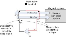
Both options do of course raise the possibility of capacitive coupling to the main coil, but by tying the pickup to the main as per my drawing earlier, you essentially remove all the capacitive coupling as it has the same potential. Capacitance only raises an issue if there is a time varying voltage difference between the windings.
Co-winding, there will only be the IR drop of the primary creating a voltage difference to the pickup.
John
If this approach is so inept, then why in Werner's work back in the late 1950's could distortion be reduced from over 20% to almost 2% using feedback from a bridge network? For example see starting on page 193 (page 13 of the pdf):
http://www.mif.pg.gda.pl/homepages/...onics_1958/1958_11_AWV_Radiotronics_23_11.pdf
For an example of the bridge I am describing see Figure 2 on page 7 of this document:
http://aerosmart.umd.edu/TechPubs/pratt_1.pdf
The title of the article is "Negative Source Impedance.... etc." Sensing current to create a negative output impedance has been discussed many times it has a pitfalls due to coil heating etc. and is prone to stability problems especially if the net resistance goes negative. There is a lot of material on this if one searches.
The bridge in effect would work at null to completely remove the back emf, think of no input and pushing on the cone, a sufficiently powerful amplifier would do whatever it could to prevent the cone from moving.
Last edited:
Another more recent patent (prior art who cares) adding DSP to the current sensing arrangement. http://sound.westhost.com/7053705.pdf
I see Mr. Elliot labors under the common misconception that ideas can be copyrighted.
I see Mr. Elliot labors under the common misconception that ideas can be copyrighted.
In no case does copyright protection for an original work of authorship extend to any idea, procedure, process, system, method of operation, concept, principle, or discovery, regardless of the form in which it is described, explained, illustrated, or embodied in such work.
Last edited:
Has anybody tried this? In theory, it should compensate for the resistive part of the voice coil. Since it does not care what R is, it should compensate compression as well.
ps...granted, the power amp at the bottom should be labelled as to which is neg, which is pos of course.
John
ps...granted, the power amp at the bottom should be labelled as to which is neg, which is pos of course.
John
Attachments
Last edited:
Has anybody tried this? In theory, it should compensate for the resistive part of the voice coil. Since it does not care what R is, it should compensate compression as well.
ps...granted, the power amp at the bottom should be labelled as to which is neg, which is pos of course.
John
Does the main PA drive the top? What impedance does it see? I bought a used speaker once with a modern very powerful 12" woofer where the VC had literally been launched out of the front of the woofer.
Does the main PA drive the top? What impedance does it see? I bought a used speaker once with a modern very powerful 12" woofer where the VC had literally been launched out of the front of the woofer.
Yes, the top terminal is the drive. The lower amp output is the return.
The main amp sees everything except the coil resistance.
John
Yes, the top terminal is the drive. The lower amp output is the return.
The main amp sees everything except the coil resistance.
John
You try it first. 😀
You try it first. 😀
That cannot happen, unfortunately.
However, it is out there in public domain.
edit: It would be simple enough to put a variable resistor between the feedback coil and the amp, such that the gain started at zero, as in no compensation, and then bring it up slowly and watch stability and waveforms.
Ah, to have a benchtop lab available...Man, I wish... I will help anybody who wants to try though...
John
Last edited:
Oh, btw. We current drive ideal inductors all the time, lots of L and zero resistance. The supplies always require compensation for the specific inductance. I do not know how the circuit I presented will act with normal power amps, as the main amp is truly driving an inductor with zero resistance.
The best part is it doesn't require a very fancy model in order to determine the correct negative resistance, it does it automatically regardless of how hot the voice coil gets.
Stability...that's for others, I did the hard part...😱
As to launching a vc out of the gap, that's easy. Ported enclosure with no low pass..
John
I do not know how the circuit I presented will act with normal power amps, as the main amp is truly driving an inductor with zero resistance.
Stability...that's for others
Sounds like a good way to send a few woofers to the Delta Quadrant.😀
True. I just present the E/magnetics theory, others can blow stuff up anyway they wish.Sounds like a good way to send a few woofers to the Delta Quadrant.😀
I was not aware that there was such a problem controlling woofers that it needs active compensation. To me, my bog standard music has far too much other content for me to even tell that my woofs is tweetin..
John
True. I just present the E/magnetics theory, others can blow stuff up anyway they wish.
I was not aware that there was such a problem controlling woofers that it needs active compensation. To me, my bog standard music has far too much other content for me to even tell that my woofs is tweetin..
John
From what I can tell there have been numerous adventures along these lines, I will bow out now since I don't particularly like a lot woof in the first place.
Why because we can.
Motional feedback: That is an interesting topic
Why would we want to do that? We already have speaker ( you know the actual driver) mechanical damping and electrical damping. We have measured and calculated driver parameters. We build complementing speaker enclosures. You would think that we have dampening the wild beast down by now?
I suppose that we DIY makers and builders do it because we can!
We can use that second voice coil to provide sensing or monitoring of the cone motion. It seems to me that using half of what was designed to be a motor to provide monitoring for what would be a sloppy under damped device to provide active braking. What is the point?
With all the wearable technology we could glue a accelerometer chip to the back of the dust cover, process the output signal and apply active braking, not too much as to over shoot the opposite direction. The result of active monitoring and damping is that the active damping is always a little late as in out of phase late if we wait to measure overshoot and then apply the brakes.
My proposed alternate if an alternate is indeed needed to overcome stored energy in the mass and spring is to measure the motional signature of the driver and add calculated negative motion at the input of the woofer's amplifier. While you are at it measure the distortion signature of the amplifier speaker system and add negative distortion at the amplifier input as well.
Think of it as push-pull thinking. (for you Scott; variable output impedance)
Why, because we can.
DT
Obviously you are not aware of the history of MFB... It has been applied by several manufacturers already. Besides, it's the best way to create a flat bass response, though relative expensive..Motional feedback: That is an interesting topic
Why would we want to do that? We already have speaker ( you know the actual driver) mechanical damping and electrical damping. We have measured and calculated driver parameters. We build complementing speaker enclosures. You would think that we have dampening the wild beast down by now?
I suppose that we DIY makers and builders do it because we can!
We can use that second voice coil to provide sensing or monitoring of the cone motion. It seems to me that using half of what was designed to be a motor to provide monitoring for what would be a sloppy under damped device to provide active braking. What is the point?
With all the wearable technology we could glue a accelerometer chip to the back of the dust cover, process the output signal and apply active braking, not too much as to over shoot the opposite direction. The result of active monitoring and damping is that the active damping is always a little late as in out of phase late if we wait to measure overshoot and then apply the brakes.
My proposed alternate if an alternate is indeed needed to overcome stored energy in the mass and spring is to measure the motional signature of the driver and add calculated negative motion at the input of the woofer's amplifier. While you are at it measure the distortion signature of the amplifier speaker system and add negative distortion at the amplifier input as well.
Think of it as push-pull thinking. (for you Scott; variable output impedance)
Why, because we can.
DT
BTW glueing the accelerometer on the back of a dustcover is the best way to get into serious trouble with this technique... 😉 It ought to be fitted on the former.
Some good people have raised an old question: why bother?
The answer is that the Rice-Kellogg shaking-cardboard driver is stupid engineering for a woofer. the mechanism is just plain Victorian in character, you are asking the driver to operate in a band with a destructive resonance plunk in the middle, and you are trying to make light materials and a weak motor behave with piston motion while transforming its heavy motion into light air.
Dumb? You bet. It is only the due to the fact that few people ever hear clean sound that we muddle along with Rice-Kellogg drivers.
The best chance to make that kind of clumsy mechanism work right is with feedback, just like all the other components.
The problem in working with feedback is not that MF is tricky but that the system we are trying to control is so yucky (and here I include the whole room acoustics in "system"). But the solution is simply to keep the feedback fraction low. Nice benefit reducing woofer distortion from 10% to 5%, even if .1% is unobtainable. And a pity there's no accepted metric for rumbling-along woofer transient mess. Here the improvement is dramatic but not readily quantifiable.
BTW, got an ACH-01-4 accelerometer in the mail today.
Ben
Last edited:
Everything in this post is wrong.
Moving coil drivers are fine devices for the purpose they are used. The resonance is not destructive, the cone is strong enough to act as a piston across most of the audible frequency band (assuming a well designed multi way speaker, the motor is sufficiently strong enough to push this piston and if you want to increase the radiation resistance of the light air you are free to use waveguides or horns.
It is not only possible, but easy to achieve the low distortion characteristics of ESL or any other type of speaker with moving coil drivers without feedback. You just have to choose the drivers carefully (some measure with remarkable stroke symmetry and low distortion on klippel and other tests), use enough cone area to keep excursion very low, well under xmax, and use proper loading devices (which could include horns, push pull driver configurations, etc).
The accepted metric for "rumbling-along woofer transient mess" is decay time, any measurement software package can measure it just fine.
0.1 percent distortion is absolutely possible from moving coil drivers without feedback. You just have to design the system properly. A properly designed system isn't going to look anything like your system though, which is probably why you are unaware that you can get fantastic results from moving coil drivers without any feedback.
Originally Posted by forr
The main concern seems to be the inductive compoment of the voice coil entering in resonance with the capactive component of the motional impedance.
They are usually labelled Le and Ces in simulation.
Le has not a constant value, it varies with both the frequency and the position of the voice coil in the gap, so one needs to be conservative when setting compensation for stability in systems using negative impedance amps.
Aren't these small enough to be ignored? Or no real obstacle to testing?
Hi Bentoronto,
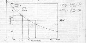
Here are some pictures you may be interested in.
The first shows the indutance variation of a driver as measured by Joseph d'Appolito, the diagram figures in his book.
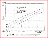
The second is the diagram of the error due to the coupling of the voice-coils in a specialised driver used by Hawksford-Mills in their famous project of a servo current driven loudspeaker.
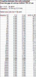
The third presents a measurement I have done a long time ago.
It shows the coupling effect in a dual voice coil extracted out of the gap of an Audax 8" driver (in fact, it was a two-layers coil which I separated to get two separated coils).
I wonder what is the effect of the magnetic flux when the twin-coil is in its intended location, inside the gap.
Attachments
Well for, you are always a monument to wonderful information. Thank you, again.
I doubt I understand 5% of what you mean to teach us. My impression from your post is that inductance and mutual-inductance aren't terribly high.
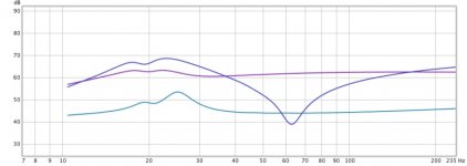
Being a very, very empirical person, first thing I did was test my new DVC driver sitting on its cardboard shipping box. I can't find the REW traces except for the crude illustration below which previously appeared in post #1, all electric signals. The straight line is the amp source, the line with the little bump is the driver impedance, and the weird line is the message from the second voice coil.
On that basis (and on looking at the really, really weird phase trace), I'd say the second voice coil is fairly well de-correlated from the first voice coil.
Also, with woofer MF, you don't want a big feedback factor. Therefore, it is no problem is the feedback signal is somewhat contaminated with the veridical drive signal. So what? Even if the cross-leakage is moderately large and unruly, it may be no problem.
If we trust the second voice coil, with feedback, my driver sitting on the cardboard box will be getting a whole lot more drive current at 62 Hz and rather less south of the resonance (after being corrected for acceleration, of course). Make sense? (Maybe not entirely.)
(I still sort of expect a basic-bridge (a single series resistor) is the best way to create a feedback signal. But this year I will be experimenting with both a DVC and an accelerometer.)
Ben
I doubt I understand 5% of what you mean to teach us. My impression from your post is that inductance and mutual-inductance aren't terribly high.
Being a very, very empirical person, first thing I did was test my new DVC driver sitting on its cardboard shipping box. I can't find the REW traces except for the crude illustration below which previously appeared in post #1, all electric signals. The straight line is the amp source, the line with the little bump is the driver impedance, and the weird line is the message from the second voice coil.
On that basis (and on looking at the really, really weird phase trace), I'd say the second voice coil is fairly well de-correlated from the first voice coil.
Also, with woofer MF, you don't want a big feedback factor. Therefore, it is no problem is the feedback signal is somewhat contaminated with the veridical drive signal. So what? Even if the cross-leakage is moderately large and unruly, it may be no problem.
If we trust the second voice coil, with feedback, my driver sitting on the cardboard box will be getting a whole lot more drive current at 62 Hz and rather less south of the resonance (after being corrected for acceleration, of course). Make sense? (Maybe not entirely.)
(I still sort of expect a basic-bridge (a single series resistor) is the best way to create a feedback signal. But this year I will be experimenting with both a DVC and an accelerometer.)
Ben
Attachments
Last edited:
I have a pair of these Sony HA-7900 MFB speakers.
Their bass sound is quite decent, especially the sense of 'control' and damping in the bass.
The schematic might give some ideas.
View attachment 534748
View attachment 534747
Dan.
Surprise! Something like these woofers just showed up in the ESL forum (don't ask) and the subtleties are explained by the always brilliant bolserst in post 61 with the full patent application attached.
http://www.diyaudio.com/forums/plan...trostatic-tweeter-repair-sony-sa-ex100-4.html
bolserst explains that for the woofers in this model, a short sensor coil is located in a long gap. In addition to generating a good feedback signal and one not correlated to the drive VC (since it is not wound over it), my guess is that Sony was keen to avoid instability if the sensor coil would find itself out of the gap because then you are in feedback hell.
The mechanics are very weird, esp the location of the sensor coil gap. In cross-section, it looks more like a Tannoy dual concentric driver from 1960 than anything else.
The patent application is absolutely impenetrable and has mostly to do with a mechanical structure thet keeps the sensor coil in place and parallel to the drive VC and why Sony is unique.
Don't miss reading this thread which features a starring role from our own just a guy in the later incarnation of this older thread recently.
I had to wire-up my ESL bias and do other ESL rebuilding. But as soon as I figure out how to characterize/measure transient behaviour, I'll be posting. It really puzzles me how to show a MF woofer is "faster" even while nobody is asking it to be playing outside its passband. For example what would be a great looking acoustical 50 Hz square wave if the passband rolled off at 120 Hz? Maybe I should just put a 50 Hz sq wave through my DSP and have a look at what comes out.
Anybody have some ideas?
Ben
Last edited:
- Status
- Not open for further replies.
- Home
- Loudspeakers
- Subwoofers
- Motional feedback: dual voice coil signal