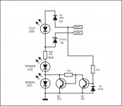
Bc556 is always on(negative base) via 22k+47k main voltage devider, so no current via led.(led dark)Hi Mile, Can you please explain how the clip indicators work? What do they sense?
When amplifier out (A.C) via 10R to bace of bc556 give a value for positive base this transistor go off.Now current pass via led .(led glow).
Last edited:
Amplifier A.C out near the power suppy voltage.How does that mean clipping?
BC546 is "locked" by voltage divider consisting of 2k2 (Ube),22k and 47k. when transistor is "locked, LED in parallel with it can not light. when a voltage out of amplifier output gets higher than Ube needed to keep transistor locked,the transistor is unlocked and LED lights.
capacitor in a circuit (i believe) serves for LED to light at more severe clipping, not in short terms. it, in my opinion serves to make a clipping indication a little bit "slower".
it is just an opinion of amateur, I would also like for Mile to explain it as proper as it should be.
capacitor in a circuit (i believe) serves for LED to light at more severe clipping, not in short terms. it, in my opinion serves to make a clipping indication a little bit "slower".
it is just an opinion of amateur, I would also like for Mile to explain it as proper as it should be.
Hi Sonal,
Do you have a schematic that matches your layout? Mine is not working and I'm having trouble finding the error without the schematic.
Thanks, Terry
Mr, Mile removed clipping indicator from his original FX100 layout. I just added one of his simple clipping indicator.
Attachments
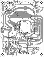
The two 2N5401 near the .1 5watt resistors in sonals pcb layout the collectors are going
to the positive rail whereas the EMITTERS should go to to the positive rail not a problem
just rotate the 2N5401 transistors
to the positive rail whereas the EMITTERS should go to to the positive rail not a problem
just rotate the 2N5401 transistors
The two 2N5401 near the .1 5watt resistors in sonals pcb layout the collectors are going
to the positive rail whereas the EMITTERS should go to to the positive rail not a problem
just rotate the 2N5401 transistors
Better look again. 2N5401 are ebc. He has them correct.
The two 2N5401 near the .1 5watt resistors in sonals pcb layout the collectors are going
to the positive rail whereas the EMITTERS should go to to the positive rail not a problem
just rotate the 2N5401 transistors
Hi Andrew,
The emitters are indeed connected to positive rail with EBC pin out for 5401.
reg
Prasi
Hello
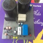
greetings many THANKS to Terry and Sonal for this FX100 PSU just confirming there
are no errors on sonals pcb works first time will post pics and small vedio to show
its working
warm regards
Andrew
greetings many THANKS to Terry and Sonal for this FX100 PSU just confirming there
are no errors on sonals pcb works first time will post pics and small vedio to show
its working
warm regards
Andrew
Hello
greetings many THANKS to Terry and Sonal for this FX100 PSU just confirming there
are no errors on sonals pcb works first time will post pics and small vedio to show
its working
warm regards
Andrew
Hi Andrew,
Great work!. What rail voltages you are using? Also, looking forward for the video.
reg
Prasi
Hello prasi
greetings tested on 50 0 50 AC transformer i used a bigger double contact 24v
relay had to change 1K2 5 watt to 1K 5watt and as the overcurrent would kick in
early 2 .1 5watt in parallel used maybe i will try to add a better 15 volt regulated
supply using LM317T /LM337T its a very nice compact power supply
warm regards
Andrew
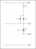
What does the diode connectd to OUT do?
Conducting, if output voltage rise up to about 2 volt stop conducting, other diode in series connect with led start conducting and led glow.
?
If Vout rises and takes the diode voltages with it, the other diode still conducts and the LED still glows.
If Vout falls to well below Pgnd, then when Vout + Vf < Vdiode+ Vled then the LED turns off.
So I ask again what does the diode to OUT do? Turn off the LED?
If Vout rises and takes the diode voltages with it, the other diode still conducts and the LED still glows.
If Vout falls to well below Pgnd, then when Vout + Vf < Vdiode+ Vled then the LED turns off.
So I ask again what does the diode to OUT do? Turn off the LED?
- Home
- Amplifiers
- Solid State
- DC Servo MOSFET Amplifier