Hi guys,
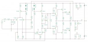
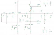
Here's a revised schematic and the measurement,
corrected zener/1N4148 at the output gates
removed T4, R23, R29
T1/R4 = 865.04uA
T2/R5 = 860.7uA
T3/R18 = 421.34uA
T5/R24 = 2.01ma
T6/R21 = -397.84uA
T10 VBE = 4.22v
T11 driver = 41.29v
T12 driver = -41.29v
T7/R15 = 277.49uA
T8/R16 = 47.25uA
@Valery ,
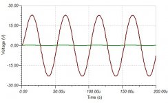
I could not find the ma measurement for the output Fets but measuring the fuses I get,
+rail fuse = -324.48uA (yes with the minus sign)
-rail fuse = +319.41uA
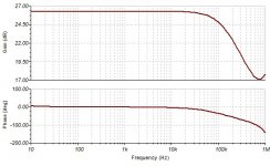
Harmonic distortion = 8.263%
DC offset = 1.9mv
P1 bias adjustment does not seem to be working 0-90% set, shows the same measurement on the outputs.
LED2 bias goes off.
Many Thanks!
Albert
The output stage is still significantly under-biased.
You have to set the quiescent current to at least 100mA for the output transistors.
Every simulator allows measuring the voltage and/or current at any point in the circuit.
The schematic, described in PDF is not good - we have already mentioned, HexFETs are not thermally stable without a spreader on the heatsink.
Maplin, mentioned above, is a different story, as it utilizes the Lateral MosFETs.
Schematic, as it is now, os generally ok. Just set P1 in the correct position, ensuring 100mA through the output devices.
OK, still working on the schematic, I actually found one old looking design with drivers arranged in quasi?...and it drives Hexfets. I made a quick simulation using IRFP240/9240 but converted the circuit into complementery one. Results looks good, at 20KHz I get 0.5% THD
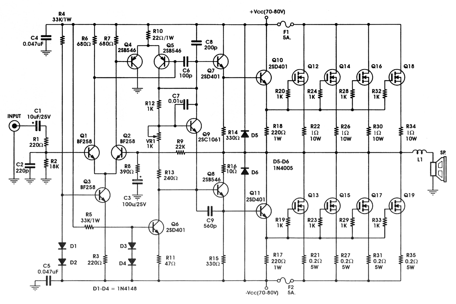
One cannot convert an amplifier designed for Lateral mosFET output stage to Vertical by just changing the devices !!!!!!!!
Yet, someone always does it on this forum, on average 2x a year. It was ever so... it just doesn't go away no matter how many times you explain it. I't the allure of simple circuits combined with confirmation bias.
Q9 MUST take account of temperature changes in the output stage.OK, still working on the schematic, I actually found one old looking design with drivers arranged in quasi?...and it drives Hexfets. I made a quick simulation using IRFP240/9240 but converted the circuit into complementery one. Results looks good, at 20KHz I get 0.5% THD
This is commonly refered to as temperature compensation for the output bias voltage.
2sb is a PNP transistor.
It's the symbol that is wrong and upside down.
And that might account for the attrocious 0.5% THD reported by the sim.
It's the symbol that is wrong and upside down.
And that might account for the attrocious 0.5% THD reported by the sim.
No, that's probably a remnant from the quasi to complementary conversion.And what about Q11? It's ok like this?
No, that's probably a remnant from the quasi to complementary conversion.
What's wrong with that? Maybe not optimal, but it will work.
Sajti
He said his model in the sim was a complementary, but he posted the quasi pic.What's wrong with that? Maybe not optimal, but it will work.
Sajti
The output devices require Vgs matching. Even 1R ballast resistors do nothing to equalise quiescent current, only forcing sharing at fairly high currents
Hello Folks,
Sorry to bother you again (and for the late response), I'm expecting a visitor today as I'm typing..a friend from a neighbouring province and who happens to own a Mobile Disco System. He will drop by my place to pick up my P3A build, we agreed on an item swap, my P3A for a brand new smartphone plus addt'l cash (I needed the phone). He will be using P3A for a small partygathering, anyway...I don't sell my amp builds and I don't get rich in audio stuff. It was a friendly favor that is all.
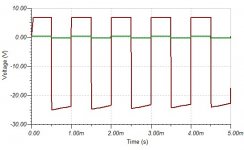
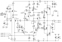
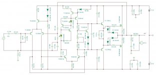
Moving on, attached is my simulation of an IRFP240/9240 based amplifier from RedFet site.The reason that I brought it up here is to clear my confusion with simulation results. This RedFet circuit was built by a local forum member and reported to be working nicely and without a problem (except for the heatsink high temp).
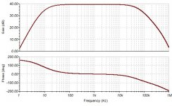
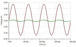
I'd like you to notice the simulation measurement and the transient graph. I got volts reading at the output resistors, not mv! Does this had to do with simulation parameters?. I'm afraid I could be possibly working blinded with my simware, if these results was working good in the actual hardware!
Most likely I am after the false results!
Amplitude = 250mv
Freq = 1KHz
Trimmer bias 50% = 26.18v
DC offset = -2.84mV
Harmonic distortion = 28.42%
IRFP240/R12 = 19.43v/58.87A
Gate Voltage = 28.48V
IRFP9240/R13 = -19.43V/58.87A
Gate Voltage = 19.38V
Sorry to bother you again (and for the late response), I'm expecting a visitor today as I'm typing..a friend from a neighbouring province and who happens to own a Mobile Disco System. He will drop by my place to pick up my P3A build, we agreed on an item swap, my P3A for a brand new smartphone plus addt'l cash (I needed the phone). He will be using P3A for a small partygathering, anyway...I don't sell my amp builds and I don't get rich in audio stuff. It was a friendly favor that is all.
Moving on, attached is my simulation of an IRFP240/9240 based amplifier from RedFet site.The reason that I brought it up here is to clear my confusion with simulation results. This RedFet circuit was built by a local forum member and reported to be working nicely and without a problem (except for the heatsink high temp).
I'd like you to notice the simulation measurement and the transient graph. I got volts reading at the output resistors, not mv! Does this had to do with simulation parameters?. I'm afraid I could be possibly working blinded with my simware, if these results was working good in the actual hardware!
Most likely I am after the false results!
Amplitude = 250mv
Freq = 1KHz
Trimmer bias 50% = 26.18v
DC offset = -2.84mV
Harmonic distortion = 28.42%
IRFP240/R12 = 19.43v/58.87A
Gate Voltage = 28.48V
IRFP9240/R13 = -19.43V/58.87A
Gate Voltage = 19.38V
Attachments
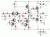

Quasi-Complementary Mod
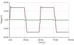
The following posts shows my other simworks taken from other design. Not much recalculation of values done just to show which one adapts much better for the IRFP240/9240 with the inclusion of drivers. I'd like to put an emphasis on the use of drivers to Hexfet outputs, member Valery and Rod Elliott. It seems integrating this addt'l stage is not an easy thing to do, taming the outputs requires more recalculation/simulation to be done.
Amplitude = 250mv
Freq = 20KHz
Harmonic distortion = 3.2619%
DC offset = -30.25mv
T10 bias 50% set = 2.12v (collector)
IRFP240/R15 = -30.24mv/47.28uA
Gate voltage = 1.07v
IRFP9240/R16 = -30.26mV/47.22uA
Gate voltage = -1.63v
Attachments
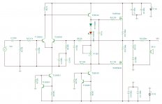
DWhite_Mod
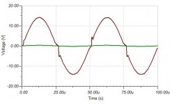
This one looks interesting...
Amplitude = 250mv
Freq = 20KHz
Harmonic Distortion = 1.6466%
DC offset = 325.81mv
IRFP240/R24 = 1.44v/2.32A
Gate Voltage = 6.05v
IRFP9240/R16 = -724.84mV/2.28A
Gate Voltage = -5.51V
T10 bias collector = 6.56v
50% adjust
This one looks interesting...
Amplitude = 250mv
Freq = 20KHz
Harmonic Distortion = 1.6466%
DC offset = 325.81mv
IRFP240/R24 = 1.44v/2.32A
Gate Voltage = 6.05v
IRFP9240/R16 = -724.84mV/2.28A
Gate Voltage = -5.51V
T10 bias collector = 6.56v
50% adjust
Attachments


member Valery and Rod Elliott.
Two Audio guru who recommends addt'l driver stage when using HexFet as outputs.
(my internet is too slow to edit back
 )
)This one looks interesting...
Amplitude = 250mv
Freq = 20KHz
Harmonic Distortion = 1.6466%
DC offset = 325.81mv
IRFP240/R24 = 1.44v/2.32A
Gate Voltage = 6.05v
IRFP9240/R16 = -724.84mV/2.28A
Gate Voltage = -5.51V
T10 bias collector = 6.56v
50% adjust
I have made D.White amp as per the schematic with single output.
It still sounds awesome and have no issues at all even running long hours.
Hello Folks,
Sorry to bother you again (and for the late response), I'm expecting a visitor today as I'm typing..a friend from a neighbouring province and who happens to own a Mobile Disco System. He will drop by my place to pick up my P3A build, we agreed on an item swap, my P3A for a brand new smartphone plus addt'l cash (I needed the phone). He will be using P3A for a small partygathering, anyway...I don't sell my amp builds and I don't get rich in audio stuff. It was a friendly favor that is all.
Moving on, attached is my simulation of an IRFP240/9240 based amplifier from RedFet site.The reason that I brought it up here is to clear my confusion with simulation results. This RedFet circuit was built by a local forum member and reported to be working nicely and without a problem (except for the heatsink high temp).
I'd like you to notice the simulation measurement and the transient graph. I got volts reading at the output resistors, not mv! Does this had to do with simulation parameters?. I'm afraid I could be possibly working blinded with my simware, if these results was working good in the actual hardware!
Most likely I am after the false results!
Amplitude = 250mv
Freq = 1KHz
Trimmer bias 50% = 26.18v
DC offset = -2.84mV
Harmonic distortion = 28.42%
IRFP240/R12 = 19.43v/58.87A
Gate Voltage = 28.48V
IRFP9240/R13 = -19.43V/58.87A
Gate Voltage = 19.38V
Hi Abetir,
Do you see the mistake in your simulation schematic?
The way IRFP9240 is connected - it will never work properly.
Other questions - what is the position of P1 rotor and what is the quiescent current of the output transistors?
As soon as you connect IRFP9240 the right way and set P1 rotor in the position, allowing around 100mA through the output transistors with no signal, you will see a working circuit with decent distortion level.
Cheers,
Valery
The following posts shows my other simworks taken from other design. Not much recalculation of values done just to show which one adapts much better for the IRFP240/9240 with the inclusion of drivers. I'd like to put an emphasis on the use of drivers to Hexfet outputs, member Valery and Rod Elliott. It seems integrating this addt'l stage is not an easy thing to do, taming the outputs requires more recalculation/simulation to be done.
Amplitude = 250mv
Freq = 20KHz
Harmonic distortion = 3.2619%
DC offset = -30.25mv
T10 bias 50% set = 2.12v (collector)
IRFP240/R15 = -30.24mv/47.28uA
Gate voltage = 1.07v
IRFP9240/R16 = -30.26mV/47.22uA
Gate voltage = -1.63v
This one is significantly under-biased - strong x-over distortion. Wrong P1 rotor position again.
This one looks interesting...
Amplitude = 250mv
Freq = 20KHz
Harmonic Distortion = 1.6466%
DC offset = 325.81mv
IRFP240/R24 = 1.44v/2.32A
Gate Voltage = 6.05v
IRFP9240/R16 = -724.84mV/2.28A
Gate Voltage = -5.51V
T10 bias collector = 6.56v
50% adjust
This one is over-biased, but more importantly - there is a mistake in your simulation schematic again - there must me a diode in series with R8 (or one more BD140, connected as a diode with CB shorted), otherwise T4 + T15 don't work as a current mirror.
Ok, corrected RedFet schematic IRFP9240, source pin to nfb output, drain pin to psu rail. Attached also was the corrected David White mod, RedFet transient graph is at 20Khz freq 250mv amplitude. I will run more sim results by tomorrow, i'm probably straining my eyes now, looks like I'm missing things'....😱🙂
My friend visitor has just left and I did a quick check on my P3A before I handed it to him, one channel seems to be biased harder than the other channel. 🙂
Did I connect the P1 rotor at DWhites schematic the correct way ?
Thanks again,
Albert
My friend visitor has just left and I did a quick check on my P3A before I handed it to him, one channel seems to be biased harder than the other channel. 🙂
Did I connect the P1 rotor at DWhites schematic the correct way ?
Thanks again,
Albert
Attachments

- Home
- Amplifiers
- Solid State
- IRFP240/9240 Amplifier (simulated on TINA)