Please have a look at section 6 Troubleshooting of the pdf document in zip file on post#1.
If you get Error 10 (Left series too low), you need to adjust Trimmer RT1 by retrying bias adjustment.
Error 20 : check A+, R+ power supplies..
Hope this helps
If you get Error 10 (Left series too low), you need to adjust Trimmer RT1 by retrying bias adjustment.
Error 20 : check A+, R+ power supplies..
Hope this helps
Maku sure your relays are also working OK. The left series are the first checks carried out and it could be that the problem isn't the LDR, but the relays.
When I first built the circuit on a breadboard, I had an issue with the fact I hadn't connected relays OK.
When I first built the circuit on a breadboard, I had an issue with the fact I hadn't connected relays OK.
Hi Vincent,
Can we use 2 boards for balanced volume control ?
One board per channel.
Hello Theodosis,
I have never tried, but I think it would be possible to use one board per balanced channel, wired as a balanced series attenuator, having one rotary encoder and one IR receiver wired to both boards... But there may possibly be balance control problems, like when one board changes to another volume level and the other one doesn't, so there should be a way to also control each channel volume separately...
How do you propose to maintain the balance of impedance between the hot and cold signals?Hi Vincent,
Can we use 2 boards for balanced volume control ?
One board per channel.
How do you propose to maintain the balance of impedance between the hot and cold signals?
That's why I am asking.
I measured the attenuation on both channels of my Vincent's LDR and found the following variations.
Are they acceptable for balanced use?
Input 1V@1kHz
Left ch. Right ch.
1 -83 -83
2 -58.4 -58.9
3 -53.3 -53.5
4 -49.5 -50.1
5 -48 -48
6 -46.1 -46.2
7 -44.5 -44.6
8 -42.7 -42.8
9 -40.9 -40.8
10 -39.4 -39.5
11 -37.4 -37.5
12 -35.7 -35.9
13 -34 -33.8
14 -32.4 -32.3
15 -30.6 -30.5
16 -29.2 -29.4
17 -27.7 -27.9
18 -26.6 -26.8
19 -25.6 -25.6
20 -24.6 -24.7
21 -23.7 -23.8
22 -23.1 -23.1
23 -22.4 -22.4
24 -21.4 -21.3
25 -20.6 -20.6
26 -19.6 -19.6
27 -19 -19.2
28 -18.6 -18.6
29 -17.8 -17.9
30 -16.9 -17
31 -16.2 -16.4
32 -15.5 -15.5
33 -14.6 -14.6
34 -13.8 -14
35 -13.1 -13.2
36 -12.4 -12.6
37 -11.6 -11.6
38 -10.8 -10.9
39 -9.95 -9.98
40 -9.22 -9.22
41 -8.33 -8.4
42 -7.48 -7.55
43 -6.7 -6.82
44 -5.86 -5.94
45 -5 -5.01
46 -4.16 -4.37
47 -3.24 -3.4
48 -2.28 -2.38
49 -1.25 -1.32
50 -0.03 -0.02
Hello Theodosis,
I have never tried, but I think it would be possible to use one board per balanced channel, wired as a balanced series attenuator, having one rotary encoder and one IR receiver wired to both boards... But there may possibly be balance control problems, like when one board changes to another volume level and the other one doesn't, so there should be a way to also control each channel volume separately...
Thank you Vincent.
I plan to use 2 encoders and 2 IR receivers side by side.
Do you think I will have channel synchronization problems ?
Not gain.
I asked
I asked
How do you propose to maintain the balance of impedance between the hot and cold signals?
Hi Vincent,
Can we use 2 boards for balanced volume control ?
One board per channel.
How do you propose to maintain the balance of impedance between the hot and cold signals?
Exactly !The gain hasn't to do with impedance?
balanced impedance requires the impedance to be balanced.
I don't know what asymmetry you have.
I asked "how do you propose to maintain the balance of impedance".
I asked "how do you propose to maintain the balance of impedance".
I don't know what asymmetry you have.
I asked "how do you propose to maintain the balance of impedance".
I have no idea, 🙂 do you have ?
That was the original question.Hi Vincent,
Can we use 2 boards for balanced volume control ?
One board per channel.
I suspect you cannot maintain impedance balance by using two unbalanced amplifiers.
I'll use two amplifier modules in full balanced configuration.
First One has voltage gain in very tight tolerances, so doesn't need to be extra matched.
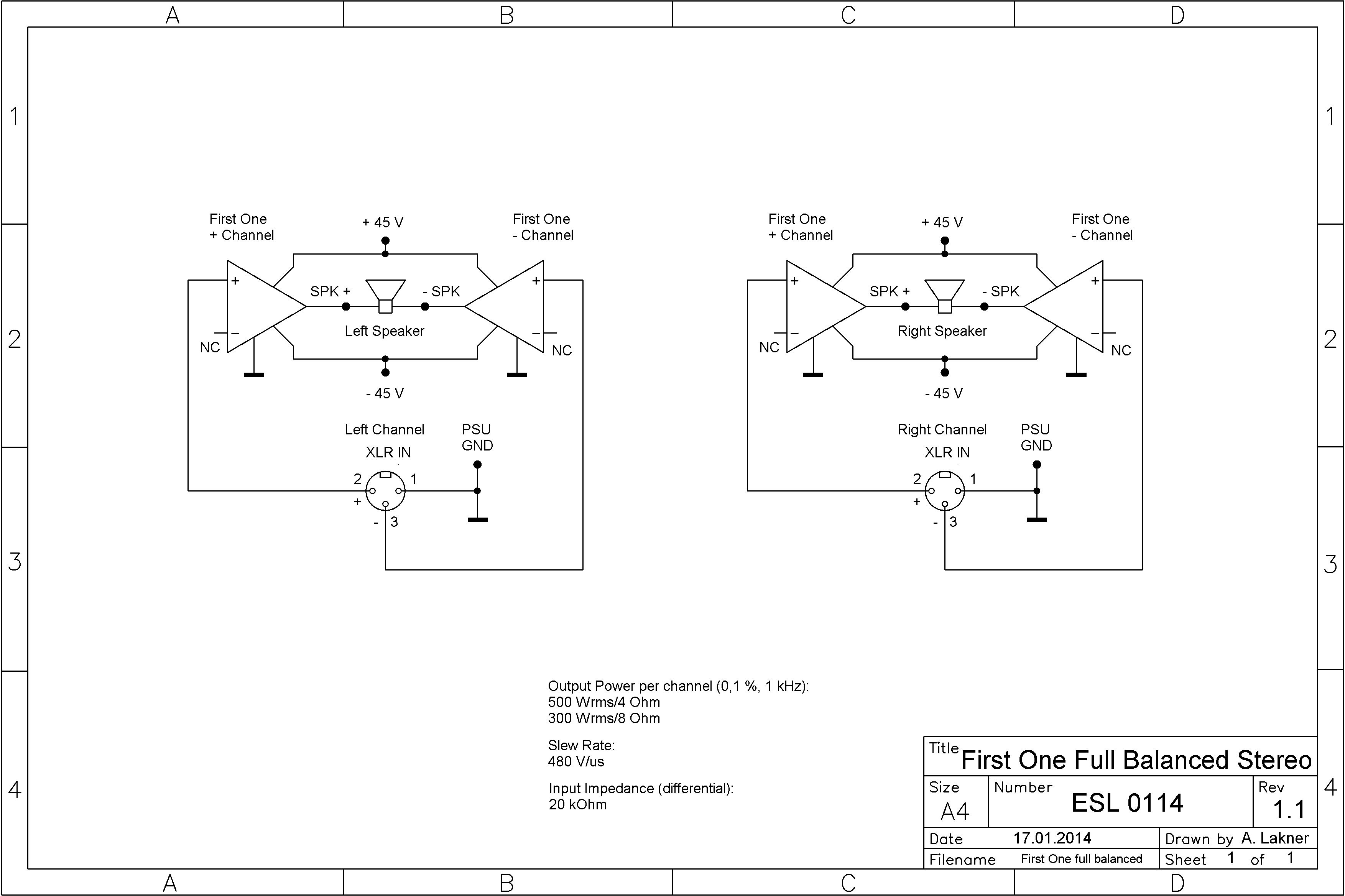
First One has voltage gain in very tight tolerances, so doesn't need to be extra matched.
Bridged and balanced are different.
I'll repeat your question:
How do you propose to maintain the impedance balance?
I'll repeat your question:
And my question:Can we use 2 boards for balanced volume control ?
One board per channel.
How do you propose to maintain the impedance balance?
And my answer:
I like the sound of LDR and would be great if I could use them with bridged F.O.
I have no idea, 🙂 do you have ?
I like the sound of LDR and would be great if I could use them with bridged F.O.
Last edited:
If you want to bridge your power amplifiers then first check they are capable of driving half load impedances safely and/or well.
Then build a 2phase circuit to drive the two amplifiers out of phase.
That is very different from using a balanced impedance connection.
Then build a 2phase circuit to drive the two amplifiers out of phase.
That is very different from using a balanced impedance connection.
If you want to bridge your power amplifiers then first check they are capable of driving half load impedances safely and/or well.
Then build a 2phase circuit to drive the two amplifiers out of phase.
That is very different from using a balanced impedance connection.
My CD player has XLR output, so I guess I don't need extra circuit for phase conversion.
Can I use just a balanced potensiometer made from LDR to control the volume ?
- Home
- Source & Line
- Analog Line Level
- Arduino based LDR volume and source selection controller