that looks fine to me....the purpose of the silicon diodes is to increase the piv rating of the rectifier...
Hi Karl,
Some of those connections could use a little more solder, and they ought to have a shiny finish. If you are using solder without lead, good luck with that.
-Chris
Some of those connections could use a little more solder, and they ought to have a shiny finish. If you are using solder without lead, good luck with that.
-Chris
Hey Chris, i have little luck with unleaded solder to get them cool down shiny...so i always look for leaded solders....
Hi AJT,
I like the lower temperatures of the leaded solder, and the higher reliability. Lead-free solder was an absolutely stupid idea.
-Chris
I like the lower temperatures of the leaded solder, and the higher reliability. Lead-free solder was an absolutely stupid idea.
-Chris
Lead-free solder was an absolutely stupid idea.
CORRECT! One of these days, a civil airliner will crash because of a tin whisker short circuit.
 The self important EU bureaucrats gave the military an exemption from the no lead ukase because their aircraft must be utterly reliable.
Rant on. RoHS = B/S!! Rant off. No lead based paint, unleaded fuel, and proper disposal/recycling of old storage batteries make perfect sense. OTOH, don't have a near terminal case of Cranio-rectal Syndrome.
BTW, homes built in the 19th Century were constructed with lead cold water pipes. Nobody got poisoned. 😉 The key word is cold. Lead salts are sparingly soluble in cold water. Do you see anyone pouring hot water on a landfill?

Karl
You need to measure the other voltages on the output tubes,especially on the control grid of the 7189s which would be a negative DC voltage..If you changed the selenium to a silicon bridge,you may have to put in a limiting resistor to lower the negative DC voltage and that way the output tubes will draw more current and therefore bring down the high B+ voltage...Try a variac of you have one just to see what happens if you run the amp in the 115vac range.
You need to measure the other voltages on the output tubes,especially on the control grid of the 7189s which would be a negative DC voltage..If you changed the selenium to a silicon bridge,you may have to put in a limiting resistor to lower the negative DC voltage and that way the output tubes will draw more current and therefore bring down the high B+ voltage...Try a variac of you have one just to see what happens if you run the amp in the 115vac range.
Michael,
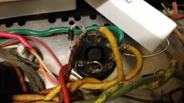
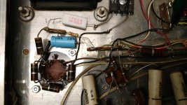
the photo shows the rectifier and wire wound resistor. This is how I purchased the amp. (Disregard the Ceracaps, they are part of the tone/balance circuits that have been bypassed.)
I think a varyac is in the cards.
Thanks again
Karl
I want you to check the voltage from pin two of each of the 7189 tubes to ground. It should be a minus voltage but tell me what the voltage is..Leave the tubes in because you aren't hurting the tubes. What I think I see from your photo is a 1k resistor which connects to the red/white wire that goes to the 7189 tubes control grid..You probably have to change that to a 5k or 10k because I believe you have way too high a negative voltage and the tubes just will not conduct properly.
Last edited:
Hi Michael,
No, to change the bias you would decrease the negative voltage, not the resistor. This is for fixed bias circuits. There isn't any current flowing in the grid circuit - or not very much.
I don't have the schematic for that amplifier, but it might also be cathode bias where the negative grid voltage is generated by current flow through the cathode resistor. Increasing those would reduce the current flowing through the tube. If they go open, you wouldn't have any current flow either.
Either way, do not change the value of the grid circuit resistors.
-Chris
.We are talking about bias and not ac signal..An obvious silicon bridge was put in place of the selenium..When you do this,the output voltage increases in the C_ minus supply and you have to many times add a resistor in place that is larger in value to lower the negative bias voltage in order for the output tubes to draw more current..When the negative Dc voltage on the control grid is too high,that suppresses electrons to flow from cathode to plate and the tube basically sits there in an almost idle state. This is why we need to know the voltage on pin 2 of the 7189s.I understand you decrease the negative voltage but putting in a larger value resistor gives you more range to reduce the bias when the bias adjustment doesn't have enough range. This is how you lower it....His B+ is way too high and if the bias pot can't bring it down,we have to lower the neg bias voltage and you do that by putting a different resistor that feeds the output tubes right off the neg bias or C minus supply as it's sometimes called.Hi Michael,
No, to change the bias you would decrease the negative voltage, not the resistor. This is for fixed bias circuits. There isn't any current flowing in the grid circuit - or not very much.
I don't have the schematic for that amplifier, but it might also be cathode bias where the negative grid voltage is generated by current flow through the cathode resistor. Increasing those would reduce the current flowing through the tube. If they go open, you wouldn't have any current flow either.
Either way, do not change the value of the grid circuit resistors.
-Chris
Last edited:
Chris I think I misspoke or I didn't clarify..
http://hhscott.com/pdf/fs/222C-C1.JPG
Here is a schematic for his amp..Notice there are no actual bias pots but there are two balance pots,one per channel.This amp should run in the neighborhood of about minus 16 volts DC..Being that silicon bridge has a lower drop than a selenium,you have to add a resistor in series with the C- supply in order to get the voltage down in the neighborhood of where it's supposed to be. This is why it is imperative that he knows the voltage reading on pin 2. When I do a Mac 30 or mc60 rebuild,I always have to remove the 3.3k bias supply resistor in the mc30s and replace it with an 8.2k to 10k because when I change the selenium to a silicon diode,the negative bias voltage goes way up and there the B+ the outputs goes from 445vdc to 480vdc and that's why I have to put a larger value resistor in to bring the negative bias down so the 480v comes down to near where it should be.
On his scott,I don't think he will be able to get it from 500v t0 420 but he can get it down to about 430v and that's where I usually get those to.
This schematic says 222 but it's the same as the LK48 because the LK48 is the Kit version is all.
Last edited:
Hi Michael,
Yes, we are talking about bias, a DC voltage. You must lower that voltage to have more bias current flowing. But resistance in series with the the grid isn't the way to do this. You must reduce the bias supply (I'll assume this is a fixed bias amplifier). The way to do that is to drop the bias supply voltage at the source to restore what the supply should have been. Series resistance to the grids may actually cause a runaway condition and instability. So leave the grid stoppers alone and work on the bias supply voltage at the source. That's before the bias pots.
Maybe we are having a translation issue here, but the OP was originally going to drop the B+ which would restore normal voltage conditions, but if the bias (C-) supply is also too high, the same idea would really benefit as it also increases the filtering action (= less ripple). That would drop the C- supply to it's normal range as well. After that, everything will be fine.
So if you were talking about increasing the value of the grid stoppers, that is not the way to go about this.
-Chris
Hi Michael,
That makes sense. We weren't communicating clearly.
I do a similar thing when restoring tube products that use a C- supply, and the B+ always needs to come down. I increase the series resistance in the B+ and that greatly improves filtering as well.
-Chris
That makes sense. We weren't communicating clearly.
I do a similar thing when restoring tube products that use a C- supply, and the B+ always needs to come down. I increase the series resistance in the B+ and that greatly improves filtering as well.
-Chris
Hi Michael,
Yes, we are talking about bias, a DC voltage. You must lower that voltage to have more bias current flowing. But resistance in series with the the grid isn't the way to do this. You must reduce the bias supply (I'll assume this is a fixed bias amplifier). The way to do that is to drop the bias supply voltage at the source to restore what the supply should have been. Series resistance to the grids may actually cause a runaway condition and instability. So leave the grid stoppers alone and work on the bias supply voltage at the source. That's before the bias pots.
Maybe we are having a translation issue here, but the OP was originally going to drop the B+ which would restore normal voltage conditions, but if the bias (C-) supply is also too high, the same idea would really benefit as it also increases the filtering action (= less ripple). That would drop the C- supply to it's normal range as well. After that, everything will be fine.
So if you were talking about increasing the value of the grid stoppers, that is not the way to go about this.
-Chris
No,what I was talking about was the source resistor in the C minus supply to bring down the C minus voltage feeding the G1 on the 7189s. After looking at the schematic I think we may have to add one which I think the 1k he has in the picture may be used for that..I just wish he would measure that voltage at pin 2 and that would give us an idea where we are at. I don't want to change the grid stoppers..
Last edited:
Hi Michael,
Yes, we agree now.
-Chris
I knew it was a miscommunication..I'm new here and I kind of speak in more abstract terms at times but as you get to know me,you will be able to fill in the blanks on what I say..
Hi Michael,
No problem. I don't understand you at times. I am an extremely literal person. Old technicians can be like that.
-Chris
No problem. I don't understand you at times. I am an extremely literal person. Old technicians can be like that.
-Chris
Hi Michael,
No problem. I don't understand you at times. I am an extremely literal person. Old technicians can be like that.
-Chris
Chris
After a while,you will be able to read between the lines with me I promise.
^ i learn a lot more from what is not being said than what was posted actually....i blame SY for that....😉
- Home
- Amplifiers
- Tubes / Valves
- LK-48 over voltage