Hi guys, I picked up a variac. When I check Vs with about 110V input all the Vs seem to fall in line. I get -19 to -20 off the #2 pins on the EL84s. When I check it at native 125V the #2s run -24 to -25. The resistor I think you were referring to, in line that supplies voltage to the balance pots checks out at just under 10k.
I have 2 big handicaps going in to this, firstly being a complete noob when it comes to circuit theory, no electrical background. Secondly this is a heavily modded amp. Thanks for all the time.
I have 2 big handicaps going in to this, firstly being a complete noob when it comes to circuit theory, no electrical background. Secondly this is a heavily modded amp. Thanks for all the time.
first thing for you to do is determine what the actual highest line voltage is in your place.
then set your variac to that voltage and take readings on the 7189 bias....
the 7189 is not the same as a 6bq5 as the 7189 can take higher plate voltages...http://www.shinjo.info/frank/sheets/106/7/7189.pdf
so if you have a 6bq5 plugged in, then you should set the bias intended for a 6bq5...http://www.r-type.org/pdfs/6bq5.pdf
a 7189 can be used for circuits using the 6bq5 easy but not the other way around, others can correct me if i am wrong...
imho, the first thing you have to look out for is tube dissipation, cathode current vs. plate voltage...(i.e. voltage from plate to cathode) and about 80% is limit although lesser can be used...i will never use the 6bq5 with more than 300 volts on the plates....
Hi guys, I picked up a variac. When I check Vs with about 110V input all the Vs seem to fall in line. I get -19 to -20 off the #2 pins on the EL84s. When I check it at native 125V the #2s run -24 to -25. The resistor I think you were referring to, in line that supplies voltage to the balance pots checks out at just under 10k.
I have 2 big handicaps going in to this, firstly being a complete noob when it comes to circuit theory, no electrical background. Secondly this is a heavily modded amp. Thanks for all the time.
Minus 25v is way too high.That will cause your B+ to go out of sight. Post a picture of the underside of the chassis and point to the resistor you are talking about that is 10k
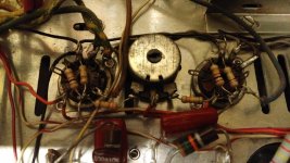
The 10k R is the 1/2W, Br,Bk,Or one physically below the WW in the photo in post 29. Here's a look at one pair of EL84 (orig. 7189) sockets and the trim pot.
One thing I just noticed: In all the schematics (I've seen 3, none exactly like what's here) there is a .01x1-1.5kV ceramic cap across the AC in just before the PT. Is that just to keep noise from the accessory outlet out? Both the outlet and the cap have been removed. (Just wondering)
As always, thanks for all the feedback.
Hi Karl,
-Chris
Yes.In all the schematics (I've seen 3, none exactly like what's here) there is a .01x1-1.5kV ceramic cap across the AC in just before the PT. Is that just to keep noise from the accessory outlet out?
-Chris
Hi AJT,
You are quite correct.
-Chris
thanks, learned that from tube gurus here in our forums...😎
btw, if that were mine will use the 6GM5 instead.....http://www.nj7p.org/Tubes/PDFs/Frank/084-Several/6GM5.pdf
Ok got it and here is what you do.
See the photo you sent? In the photo you have the balance pot and the center pin of that pot has a red/white wire going to it that goes back to the c minus supply and it hooks to the negative side of that little blue capacitor..You need to cut the red/white wire that goes to the blue capacitor and insert a 10k resistor in series with the blue cap and the red/white wire..This will bring down the negative bias voltage and allow the output tubes to draw more current and therefore bring down the 500v by about 50vdc or more...Your blue capacitor is not in this photo but it is in another photo...Take a photo of the whole bottom side and you can see it.
Call me at XXX XXX XXXX and i can explain it more.
Edit: Number removed at member's request.
Here
See the photo you sent? In the photo you have the balance pot and the center pin of that pot has a red/white wire going to it that goes back to the c minus supply and it hooks to the negative side of that little blue capacitor..You need to cut the red/white wire that goes to the blue capacitor and insert a 10k resistor in series with the blue cap and the red/white wire..This will bring down the negative bias voltage and allow the output tubes to draw more current and therefore bring down the 500v by about 50vdc or more...Your blue capacitor is not in this photo but it is in another photo...Take a photo of the whole bottom side and you can see it.
Call me at XXX XXX XXXX and i can explain it more.
Edit: Number removed at member's request.
Last edited:
The 10k R is the 1/2W, Br,Bk,Or one physically below the WW in the photo in post 29. Here's a look at one pair of EL84 (orig. 7189) sockets and the trim pot.
One thing I just noticed: In all the schematics (I've seen 3, none exactly like what's here) there is a .01x1-1.5kV ceramic cap across the AC in just before the PT. Is that just to keep noise from the accessory outlet out? Both the outlet and the cap have been removed. (Just wondering)
As always, thanks for all the feedback.
Karl
The 10k I speak of is not in there..It has to be added because you no longer have a selenium rectifier which has a bigger voltage drop..Unless you put a selenium back in,you have to put a resistor in there to limit the voltage out of the C minus supply.
Mike is correct about the forward drop in selenium being greater than that in silicon. A dropping resistance increase is needed to bring the C- rail voltage value back into specification.
If the bias supply rail voltage is too "tall" the tubes can be completely cut off.
If the B+ supply is not properly loaded down by O/P tube "idle" current draw, it will naturally read high.
If the bias supply rail voltage is too "tall" the tubes can be completely cut off.
If the B+ supply is not properly loaded down by O/P tube "idle" current draw, it will naturally read high.
Michael et all,
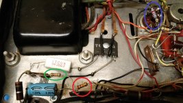
So I added the 10K resistor (red circle) between the cap and the balance pot.
The other 10K resistor (green circle) has always been there. I am sorry to report that it did virtually nothing, grid Vs still in the -18 to -19 range running the amp at 110V off the variac. As you can tell there is a cheap replacement 1.2K (blue circle) feeding the grid in the first power tube. I took it upon myself to sub in a number of different resistors just to see what value it would take to bring it down to the -14V range. It finally dropped below -15V with a 1 Mega ohm in place of the 1K. That says there is very little current, right? Less than 0.005mA?
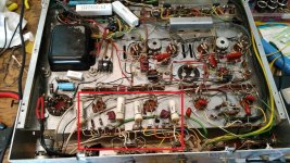
I also included a photo of the whole bowl of audio spaghetti! The red square shows the circuits that are bypassed.
So I added the 10K resistor (red circle) between the cap and the balance pot.
The other 10K resistor (green circle) has always been there. I am sorry to report that it did virtually nothing, grid Vs still in the -18 to -19 range running the amp at 110V off the variac. As you can tell there is a cheap replacement 1.2K (blue circle) feeding the grid in the first power tube. I took it upon myself to sub in a number of different resistors just to see what value it would take to bring it down to the -14V range. It finally dropped below -15V with a 1 Mega ohm in place of the 1K. That says there is very little current, right? Less than 0.005mA?
I also included a photo of the whole bowl of audio spaghetti! The red square shows the circuits that are bypassed.
Attachments
Hi Karl,
Neat work, but you really want to get some "spaghetti" over the leads from the bias rectifier, like right now! You lose bias and everything will turn red in a hurry, and with luck, blow a fuse.
Needless to say, 1M0 is too high for a grid stopper. Like what I said earlier. You can make a voltage divider for your bias supply to drop it into the right ballpark. That is by far the best way to go about this.
-Chris
Michael et all,
So I added the 10K resistor (red circle) between the cap and the balance pot.
The other 10K resistor (green circle) has always been there. I am sorry to report that it did virtually nothing, grid Vs still in the -18 to -19 range running the amp at 110V off the variac. As you can tell there is a cheap replacement 1.2K (blue circle) feeding the grid in the first power tube. I took it upon myself to sub in a number of different resistors just to see what value it would take to bring it down to the -14V range. It finally dropped below -15V with a 1 Mega ohm in place of the 1K. That says there is very little current, right? Less than 0.005mA?
I also included a photo of the whole bowl of audio spaghetti! The red square shows the circuits that are bypassed.
The total current in the bias string after a quick schematic consult is roughly 330uA based on stock voltage values. Where are you measuring the bias voltage values? Most of these amps had at least -20V or so on the control grids as a result of the very high plate voltage and screen voltage. What is the voltage across each 10 ohm cathode resistor? You should have approximately -48V at the top at one end of the bias pot and pretty close to -40V on the other. I've worked on these amps in the past and I am little confused by the direction you are taking.
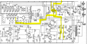
Schematic here:
https://www.google.com/url?sa=t&rct=j&q=&esrc=s&source=web&cd=1&ved=0ahUKEwjxyo7JpezKAhVMdD4KHXg7DGAQFggdMAA&url=http%3A%2F%2Fvintagevacuumaudio.com%2Fschematics-manuals%2Fhh-scott%2Fhh-scott-lk48-b-schematics.pdf&usg=AFQjCNHUHGA5JShXb2tuKDLjxhVdK96q2g&sig2=qA3Uk3_4hilq5L9ZyB8LCg&cad=rja
Attachments
Thanks Chris,
None of the build credit goes to me. I'm just trying the next step from my kit builds, and hopefully learn a little along the way.
The EE at work said the same about the value of the grid stopper, it was mostly an exercise.
None of the build credit goes to me. I'm just trying the next step from my kit builds, and hopefully learn a little along the way.
The EE at work said the same about the value of the grid stopper, it was mostly an exercise.
Kevinkr,
this LK is closer to a 299c-c1, at least this portion. I'm just trying to bring what I discovered to be high voltages back into line with published values. Unfortunately I purchased it working and don't know what the parameters were, I just enjoyed the music before the part failures that led me down this path. I appreciate everyone's insight into this.
this LK is closer to a 299c-c1, at least this portion. I'm just trying to bring what I discovered to be high voltages back into line with published values. Unfortunately I purchased it working and don't know what the parameters were, I just enjoyed the music before the part failures that led me down this path. I appreciate everyone's insight into this.
Correct,that says there is very little current being drawn..Kevin mentioned about the tubes running -20v and he is right when the B+ is up where you have it..Most 7189 amps thp are running minus 17 to minus 19v like on the Sherwood s5000s.Michael et all,
So I added the 10K resistor (red circle) between the cap and the balance pot.
The other 10K resistor (green circle) has always been there. I am sorry to report that it did virtually nothing, grid Vs still in the -18 to -19 range running the amp at 110V off the variac. As you can tell there is a cheap replacement 1.2K (blue circle) feeding the grid in the first power tube. I took it upon myself to sub in a number of different resistors just to see what value it would take to bring it down to the -14V range. It finally dropped below -15V with a 1 Mega ohm in place of the 1K. That says there is very little current, right? Less than 0.005mA?
I also included a photo of the whole bowl of audio spaghetti! The red square shows the circuits that are bypassed.
So you are saying that the 10k resistor that was added in the C minus supply did nothing to bring it down but a 1 meg brought it down? Where did you insert the 1 meg..I'm beginning to wonder if your output tubes are weak.
The important thing is how much voltage is developed across those 10 ohm cathode resistors as it tells you what the output stage current is. I'm assuming they or something similar is there.
A volt across that resistor would indicate 100mA of combined plate and screen current. (Too high even for a 7189 but not far removed from where these tubes were run - way beyond their dissipation ratings) In a similar application the only modern tubes I've found that survive are Russian 6P14P-EV or ER, and even they need a little help.
A volt across that resistor would indicate 100mA of combined plate and screen current. (Too high even for a 7189 but not far removed from where these tubes were run - way beyond their dissipation ratings) In a similar application the only modern tubes I've found that survive are Russian 6P14P-EV or ER, and even they need a little help.
The 10K inserted at the red circle in post #53 brought the grid voltage down about 0.1V as measured from pin 2 to ground. The 1meg was swapped in at the grid, in place of the 1k, just to see what it would take to directly bring the voltage down to the published values for the EL84 tubes.
If as you both pointed out that 7189s typically run at -17 to -19 V, then with a bucking transformer and a set of EL84Ms this long thread my have only been about you all schooling me a little, something I could sorely use and truly appreciate.
If as you both pointed out that 7189s typically run at -17 to -19 V, then with a bucking transformer and a set of EL84Ms this long thread my have only been about you all schooling me a little, something I could sorely use and truly appreciate.
- Home
- Amplifiers
- Tubes / Valves
- LK-48 over voltage