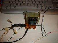
Nice little transformer but why replace the better suited wire-wound surge resistors with MF types?
Double-checked and they are stated as being wirewound despite their appearance:
http://cpc.farnell.com/multicomp/mc...d&selectedCategoryId=&categoryId=700000011439
I think it unlikely the " sound " of the long tail pair will change much by looking at the pentode like transistor curves. The way the LTP drives the VAS stops that being a reality. Hiss could change things a bit. The final reason is feedback. This stage and the amplifier as a whole sound as it does due to the VAS capacitor, VAS and feedback. The current the LTP is run at is also a factor ( not easy to say for certain how it should be ). The VAS transistor will be very important. I see nothing of note wrong with the output stage.
Naim charging £55 for BC239 will be part of why in the end only rich silly people buy from them. A shame because back in time Naim was good value. Buy a Marantz Model 9 if rich and silly, it will go up in value when you get bored.
Naim charging £55 for BC239 will be part of why in the end only rich silly people buy from them. A shame because back in time Naim was good value. Buy a Marantz Model 9 if rich and silly, it will go up in value when you get bored.
Wire wound when using thick guage wire have a high overload capability. I think that thin wire, wire wounds are not quite as good.It's more that I don't trust the originals, given the cost of the board. I replaced them with what I already had in stock.
The unit is working well, the amp is left on all the time so I'd expect the resistors to pass current maybe half a dozen times a year. During testing the power was cycled a dozen times and the resistors didn't feel particularly warm. The delay time is set to 3s.
What would be the advantages of wirewound parts?
Metal oxide have a fairly high overload capability. I think this comes from the ~10 times thicker film compared to a metal film.
Metal film has the lowest overload capability.
On the basis that high thermal capacity of the wire/film is good for overload capability I use the metal oxide, or thick wire wire wounds in series, to arrive at the required added resistance for effective current limiting.
eg. one needs 40r of added resistance to soft start a transformer.
One can use a 50W metal clad 39r, or 5off 10W 180r or 220r, or 5off 10W 10r
I would choose the 5off 10r for that duty becuase I believe the series string of 10r resistor has the highest overload capability and that equals highest reliability on repeated cold starts.
Why do we need high overload capability?
A soft start of 40r on a 230Vac supply with 2r of primary resistance will typically see a peak starting current of ~7.7Apk, or for one cycle 5.5Aac
The effective average power dissipated in the 50W of added resistance for that one cycle is 1200W, i.e. 24 times the resistor power rating.
That is a severe duty. That duty is never described, nor detailed, in the resistor datasheets. Typically the datsheets look at +50% overload or +100% overload, not +2300% overload.
I gave some of this information to the DIYaudio Forum's soft start Thread. They chose to ignore the concern.
BTW, that one cycle severe overload does not heat the resistor all that much. there is a lot of thermal capacity in the wire/oxide of the resistor.
I typically use 20W to 30W of series connected oxide resistors in my soft starts (20 to 40times power rating for the one cycle overload) and have never (yet) had any failures.
Last edited:
If they are wire wound you will be able to see the thick wire profile under that coating.Double-checked and they are stated as being wirewound despite their appearance:
http://cpc.farnell.com/multicomp/mc...d&selectedCategoryId=&categoryId=700000011439
If they are using very thin wire in a high value resistor, then you will not see the wire profile.
If they are metal oxide film, it is unlikely you will see the gaps between the spirals of the film.
Vishay do show some high overload data in a SMA datasheet.
Overload Test Short time overload at 6.25 x rated power
≤ ± 0.1%
IEC 60115-1 4.13 2 seconds for size 0204 and 5s for sizes ≥ 0207
On the subject of overload duration, I note that howarthcd was using a delay of 3 seconds for the soft-start switch. Optimum is around only 100 milliseconds, allowing 5 full 50Hz mains cycles of surge limiting at power up, so what's the purpose of 3 seconds?
I can see now, that if thin metal tape was used to wind those resistors, it could be concealed by the coating seen in the pics and look much like a typical MF resistor. The problem though, is that the thinner the metal, the more it behaves like a film resistor and loses the durability benefits of wire. Personally, I would use a cheap ceramic block resistor every time in a harsh duty like that - no matter whether it is operated several times every day or near redundant, as suggested by the few times per year of operation.

I can see now, that if thin metal tape was used to wind those resistors, it could be concealed by the coating seen in the pics and look much like a typical MF resistor. The problem though, is that the thinner the metal, the more it behaves like a film resistor and loses the durability benefits of wire. Personally, I would use a cheap ceramic block resistor every time in a harsh duty like that - no matter whether it is operated several times every day or near redundant, as suggested by the few times per year of operation.
Andrew did a very intersting study of that. Hope he doesn't mind saying again. If I read him correctly he says the lamp limiter shows some few seconds to be about right.
Andrew did a very intersting study of that. Hope he doesn't mind saying again. If I read him correctly he says the lamp limiter shows some few seconds to be about right.
This was the basis of the selection of a 3s delay as this was about the time it took for the lamp to fully extinguish following power-up.
If you also have a bulb limiter fitted, this is quite a different matter since its hot resistance is much higher than the soft start and will stifle any inrush current to the amplifier. Whilst ever you have a bulb limiter fitted, the soft start device is completely redundant.
The soft start in this case is simply a switch that is powered and operates independently of the amplifier. Does it matter at all if it shorts out its surge resistors after 100ms and the bulb then takes over all the limiting as expected? Permanently altering its normal operation timing to 3 seconds doesn't achieve anything for normal amplifier operation nor for using the bulb limiter, as it won't operate normally until the full mains voltage is available. Further delaying this seems pointless all round but perhaps I've missed something.
The soft start in this case is simply a switch that is powered and operates independently of the amplifier. Does it matter at all if it shorts out its surge resistors after 100ms and the bulb then takes over all the limiting as expected? Permanently altering its normal operation timing to 3 seconds doesn't achieve anything for normal amplifier operation nor for using the bulb limiter, as it won't operate normally until the full mains voltage is available. Further delaying this seems pointless all round but perhaps I've missed something.
In the interest of science Ac to Dc ?
I built a bridge rectifier from some diodes I had to convert 29VAC to DC and ended up with 26VDC, the expected approx .7 volt per diode loss in the transformation. My question, using the 25 volt AC secondary output from a toroidal transformer how will I be arriving at the prescribed 40VDC for the amplifier board? Should I be using a 40VAC output from the transformer in the first place. Behold my first born circuit. Thanks
I built a bridge rectifier from some diodes I had to convert 29VAC to DC and ended up with 26VDC, the expected approx .7 volt per diode loss in the transformation. My question, using the 25 volt AC secondary output from a toroidal transformer how will I be arriving at the prescribed 40VDC for the amplifier board? Should I be using a 40VAC output from the transformer in the first place. Behold my first born circuit. Thanks
Attachments

I built a bridge rectifier from some diodes I had to convert 29VAC to DC and ended up with 26VDC, the expected approx .7 volt per diode loss in the transformation.
Add an capacitor to that across +/- Vdc and it will show the filtered vdc value.
The question is a little bit more complicated than it appears. Usually the mains is taken to be a nominal 230 VAC ( 117 VAC USA, often now said to be 115 VAC +/- 10% ). That for safety has to be thought to be 253 VAC. A typical small transformer about 11 % regulation. If we take 25 VAC x 10% ( 253 VAC ) x 11 % we get about 30.5 VAC. That would be about 43.2 VDC without rectifier loss. If we say 0.6 VDC rectifier loss at the very small standby current that is about 1.2 V in the typical bridge circuit. That suggests about 42 VDC. In my house my typical supply is 243 VAC. On load the 25 VAC type gives about 37 VDC. That is fine with 50 VDC capacitors and shows no obvious problems with 40 VDC types even. 25 VAC seems as far as I would dare go.
The logical solution is to run lets say 30 VAC and 63 VDC capacitors to TR7/8/9/10. Run all the other transistors at +/- 39 VDC from a regulated supply. The transistors below are at worse 20 MHz, RS say 1 MHz. Even so 1MHz is as fast as any typical ready made regulator that often won't be safe at 50 V. If used in the amplifed zener type it is a painless way to make a very usable regulator. I was told in 1972 never to think of using one as the ready made would be better. That was the the most unwise advice I was ever given. If no regulator is used the amplified zener is already 100's of time better. The little bit of hiss they produce can be filtered. The big advantage ( very big ) of this is the amplifer becomes ideal in how it works. That means the VAS clips before the output transistors which sounds much nicer. The output transistors can never show the ripple mixed into the music. That is because the TR1/2/3/4/5/6/ see a near pure DC supply and the voltage headroom of the TR7/8/9/10 form a secondary regulator effect. The ouput stage will get slightly hotter. Also to my way of thinking the TR7/8/9/10 need to be 200 V types.
Andrew and I were on a very long thread some time ago about amplifer settling times after switch on. Whilst 20 mS seems likely the actual times can be longer. I forgot all the reasons given. CVT transformers are said to use this principle to function. Whilst the standard mains transformer is not much like a CVT it suggests a larger time period is prudent. A toroid will instantly saturate on swithc on ( this can blow fuses ). In fact when running they are very close to that. It is not hard to think that situation takes 3 complete waves to pass ( 60 mS ). 3 seconds is wise. I suspect they use 3 seconds so as to show something did happen. If not the sound of the primary switch and the transformer thump will hide the relay click.
Regulated Power Supplies
Possible choices.
KSC2383YTA | Fairchild KSC2383YTA NPN Bipolar Transistor, 1 A, 160 V, 3-Pin TO-92 | Fairchild Semiconductor
KSA916YTA | Fairchild KSA916YTA PNP Bipolar Transistor, -800 mA, -120 V, 3-Pin TO-92 | Fairchild Semiconductor
BZX85C39V | Magnatec BZX85C39V Zener Diode, 39V 5% 1.3 W Through Hole 2-Pin DO-41 | Magnatec
I suspect that the extended time constant is to provide some modicum of slow charging. I don't think that retaining a high source resistance to the transformer is a particularly effective slow charge method. Secondary resistance in the smoothing capacitors' charging circuit is the acknowledged "best" method.On the subject of overload duration, I note that howarthcd was using a delay of 3 seconds for the soft-start switch. Optimum is around only 100 milliseconds, allowing 5 full 50Hz mains cycles of surge limiting at power up, so what's the purpose of 3 seconds?
I opened up a damaged ceramic cased wirewound to discover it was a metal oxide helix wound/cut on a very small diameter ceramic substrate with pressed on metal end caps welded to copper tails.I can see now, that if thin metal tape was used to wind those resistors, it could be concealed by the coating seen in the pics and look much like a typical MF resistor. The problem though, is that the thinner the metal, the more it behaves like a film resistor and loses the durability benefits of wire. Personally, I would use a cheap ceramic block resistor every time in a harsh duty like that - no matter whether it is operated several times every day or near redundant, as suggested by the few times per year of operation.
It could have been called a thick film, or metal oxide film, but certainly not a wire wound.
Whereas another I opened was indeed a wirewound.
In both cases I calculated the inductance of the stretched multi-turn small diamter coil to discover neither were "low inductance".
Had both used a larger diameter substrate and fewer turns in the coil, then they may have been claimed as lower inductance. Neither used the opposing turns method to reduce effective inductance.
A laser cut film could very easily be a opposing double helix type to reduce inductance. Has anyone seen these advertised, or claimed by the manufacturer?
Last edited:

In this diagram outputs are TR9/10/11/12 ( preferably 250 V types as is common ). I always forget the TR7/8 protection current limiters as I tend not to fit them.
I am assuming the voltage to be 50 VDC ( from circa >30 VAC ). I am saying 10 VDC loss via the resistor ( and transistor ) . 10/470 = 22 mA. 22mA x 39 V = <1W. All approximate as the exact points will vary. In theory one could use far less current, if so a more complex circuit is required. Silly to ruin the simplicity. I haven't put in filter caps as the net has examples. The resistors will be at about 0.25 watt. This should be better than the NAP 250 in every respect.
The amplified zener unlike conventional regulators should have no stability problems. The analogy is it will turn the river water quality raw DC into the purest domestic water. The regulators we buy take it a stage further to processing water quality for chemicals. We don't need that. To be clear what we usually use is river water quality. If is said 4 layers cotton material will filter river water to be drinkable in terms of bacteria. Rather you than me. The better PSU's seen here are not even 4 layers of cotton in this analogy.
One of the reasons to use a 500 VA transformer is the regulation is better. A 25 VAC 500 VA should be ultra safe. All the same this idea has great potential. Make the regulator up and use a 1K5 resistor to simulate the load, test for at least 24 hours. For this idea 30 VAC @ 500 VA has merit. The greater merit is between 160 VA and 500 VA it is likely the casework is the bigger money question.
Just fixing a Kenwood KA660D. It says 200VA power use ( assume 300 VA transformer ) fused at 2.5AT. It is an E&I type that usually has less switch on current than a toroidal. 2.5 x 240 V = >600 VA if 253VAC. The mighty Kenwood have to do what we all do and play a little unsafe. DC offset is 100 mV! As the amp is happy I have to assume it's standard. Kenwood are specail people. I always trust their designs.
The more that Less posts the more convinced I am that he/she should not be let loose on mains powered projects.I built a bridge rectifier from some diodes I had to convert 29VAC to DC and ended up with 26VDC, the expected approx .7 volt per diode loss in the transformation. My question, using the 25 volt AC secondary output from a toroidal transformer how will I be arriving at the prescribed 40VDC for the amplifier board? Should I be using a 40VAC output from the transformer in the first place. Behold my first born circuit. Thanks
I use two relays in my remote start and soft start................ I suspect they use 3 seconds so as to show something did happen. If not the sound of the primary switch and the transformer thump will hide the relay click.
The first relay sends power to the main transformer via the soft start. The second relay bypasses the soft start resistors after ~200ms delay after power ON. I can clearly hear the double click of the sequenced relays.
The first relay is switched on after power is applied to the auxiliary transformer (fed with an F500mA fuse) AND the two N.C. heatsink temperature switches AND the remote low voltage ON/OFF switch all become closed.
There is no apparent transformer "thump" because the soft start resistance current limits the start up current to enable the close rated mains fuse to not suffer nuisance blowing.
Last edited:
I would use transistor here that are rated with Vce0 > worst case rail to rail voltage. For a nominal +-50Vdc supply that worst case will be ~ 110Vdc. i.e. 120Vce0 is adequate.
In this diagram outputs are TR9/10/11/12 ( preferably 250 V types as is common ). I always forget the TR7/8 protection current limiters as I tend not to fit them.
What I find of far more relevance is adequate SOA at Vce= rail voltage.
Choosing transistor for both driver duty and output duty that have adequate current capability when warm/hot at the supply rail voltage determines whether the devices will blow up during highly stressed operation.
Most driver and output devices have an SOA that is down to around 50% of the Pmax when Vce is 60Vce
I posted some values for 2sa1943/c5200 this morning.
Here we have a 150W Pmax and 230Vceo, yet it has become a 68W device @ 70Vce (well below 50% of max Vceo)
Compare to the exceptional 2n3773. Which has a guaranteed 1.5A @ 100Vce, ie. full Pmax right up to 100Vce and yet has a low 140Vceo. This would be very suitable for a +-60Vdc supply.
This shows that SOA @ supply rail voltage is far more significant as design criteria, than the very high Vceo.
Last edited:
lucpes, I didn't refine my rectifier it was for a learning experience to see the results of the AC to DC conversion however I do want to use it. It produces 5v 9v 11v 15v and 29v can you recommend cap values to stabilize the voltages for use as a dc supply for fooling around with, Thanks
I am not well grounded Andrew so mains are not a issue. I do greatly appreciate your input to my questions concerning my project and it does supply me with many opportunities to try to figure out just what the hell you are trying to tell me, how ever I still do not know where my 25 volts turns into 40 volts. I did get a telling response from atupi concerning my question. I think the old "keep it simple stupid" approach as a initial answer to Sufi my ignorance will be more helpful and then if you have the time to type I have the time to read. So take your blood pressure medicine and prepare for more. Maybe a sub thread is in order "FOR DUMMIES" P/S I'm a He, and signing up for a junior college course in guess what?The more that Less posts the more convinced I am that he/she should not be let loose on mains powered projects.
- Home
- Amplifiers
- Solid State
- NAP-140 Clone Amp Kit on eBay