I found this (pff... already 10 years old...) topic a few days ago:
http://www.diyaudio.com/forums/solid-state/57262-phase-accuracy.html#post643857
and find some interesting posts about FB and its tasks, may be worth reading for you as well.
http://www.diyaudio.com/forums/solid-state/57262-phase-accuracy.html#post643857
and find some interesting posts about FB and its tasks, may be worth reading for you as well.
The velocity factor of an electric current through a conductor is typically 40 to 90 % of C and highly dependent on the conductors insulation properties (I.e the surrounding sheath). For an amplifier PCB, distributed L and C are low, so current propagation through the circuit is at the upper limit.
Delays of 220ns imply a round trip of around 60 or 70 meters. Does not seem correct.
Secondly, there are a lot of plots of voltage. We should be looking at the current waveforms.
I would expect the total propagation delay to be in the low to mid single digit ns.
What am I missing here?
Delays of 220ns imply a round trip of around 60 or 70 meters. Does not seem correct.
Secondly, there are a lot of plots of voltage. We should be looking at the current waveforms.
I would expect the total propagation delay to be in the low to mid single digit ns.
What am I missing here?
Doesn't matter how much you hand wave and troll, microstrip is still irrelevant for audio, by a large margin. Quoting microstrip design in the context of audio doesn't make you look smarter. Oh, and the linear approximation (locally, aka "small signal") method is still valid and confirmed billions of times every day. If one is concerned about "large signal" behaviour, the simple way is to move the locality (e.g. the bias point) toward the limits and repeat the small signal (linear) analysis. It will still be perfectly valid around that new vicinity. In fact, analyzing the stability when the output approaches the rails is a standard design technique.
Yes, I'm sure there are plenty of reputable amplifiers that may burst into oscillations when the output approaches the rails, this is simply "bad design" in my book, not a flaw of the small signal analysis method.
If one is concerned about "large signal" behaviour, the simple way is to move the locality (e.g. the bias point) toward the limits and repeat the small signal (linear) analysis.
What you're describing is not "large signal" analyisis. It's actually a pretty braindead way of trying to achieve it.
Yes, I'm sure there are plenty of reputable amplifiers that may burst into oscillations when the output approaches the rails, this is simply "bad design" in my book, not a flaw of the small signal analysis method.
The method you previously described is a sure way of producing plenty of "bad designs".
The velocity factor of an electric current through a conductor is typically 40 to 90 % of C and highly dependent on the conductors insulation properties (I.e the surrounding sheath). For an amplifier PCB, distributed L and C are low, so current propagation through the circuit is at the upper limit.
Delays of 220ns imply a round trip of around 60 or 70 meters. Does not seem correct.
Secondly, there are a lot of plots of voltage. We should be looking at the current waveforms.
I would expect the total propagation delay to be in the low to mid single digit ns.
What am I missing here?
I was trying to point to that. How a RC circuit can have a time delay of 200 ns?
What you're describing is not "large signal" analyisis. It's actually a pretty braindead way of trying to achieve it.
The method you previously described is a sure way of producing plenty of "bad designs".
I am sure you have a much better method for analyzing and designing feedback circuits, come up with it and educate us the unwashed masses.
I would be in particular curious how you would implement the Lyapunov, Popov or single perturbation method in the audio design space, and what would be the net benefits compared to the "braindead ways" that everybody uses, some even without realizing it.
Ok, not sure why I'm wasting my time here.
I am sure you have a much better method for analyzing and designing feedback circuits, come up with it and educate us the unwashed masses.
Sure, google "modern control theory" and a few good books and papers will pop up.
I would be in particular curious how you would implement the Lyapunov, Popov or single perturbation method in the audio design space, and what would be the net benefits compared to the "braindead ways" that everybody uses, some even without realizing it.
Sure, google "modern control theory" and a few good books and papers will pop up.
Otherwise said "I'm still trolling and I'm proud of it, I believe it makes me look smart".
Dadod
Here's my attempt at the maths:
Why does an RC time constant give a delay?
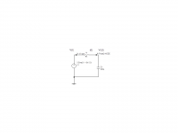
Consider the RC circuit attached. V(t) is the input, i(t) the current through the resistor and Vc(t) the voltage on the capacitor, all a function of time.
The current in the resistor (omitting the (t) for clarity)
i=(V-Vc)/R
but also
i=C dVc/dt
Equating these
RC dVc/dt=V-Vc
or
V=Vc+RC dVc/dt
Now if Vc is a sinewave of unity amplitude
V=sin(ωt)+ω.RC.cos(ωt)
But
sin(ω(t+τ))=sin(ωt).cos(ωτ)+cos(ωt).sin(ωτ)
For a small tau, sin(ωτ)=ωτ and cos(ωτ)=√(1-〖sin(ωτ)〗^2 ). And if ωτ is small, cos(ωτ) is almost equal to 1. This makes the equation above equal to the previous equation if
τ=RC. So for all frequencies where ωτ is small the RC network produces a signal delay equal to RC.
At higher frequencies then the approximation ωτ=small fails and then you see significant attenuation and phase shift.
Here's my attempt at the maths:
Why does an RC time constant give a delay?
Consider the RC circuit attached. V(t) is the input, i(t) the current through the resistor and Vc(t) the voltage on the capacitor, all a function of time.
The current in the resistor (omitting the (t) for clarity)
i=(V-Vc)/R
but also
i=C dVc/dt
Equating these
RC dVc/dt=V-Vc
or
V=Vc+RC dVc/dt
Now if Vc is a sinewave of unity amplitude
V=sin(ωt)+ω.RC.cos(ωt)
But
sin(ω(t+τ))=sin(ωt).cos(ωτ)+cos(ωt).sin(ωτ)
For a small tau, sin(ωτ)=ωτ and cos(ωτ)=√(1-〖sin(ωτ)〗^2 ). And if ωτ is small, cos(ωτ) is almost equal to 1. This makes the equation above equal to the previous equation if
τ=RC. So for all frequencies where ωτ is small the RC network produces a signal delay equal to RC.
At higher frequencies then the approximation ωτ=small fails and then you see significant attenuation and phase shift.
Attachments
So for all frequencies where ωτ is small the RC network produces a signal delay equal to RC.
At higher frequencies then the approximation ωτ=small fails and then you see significant attenuation and phase shift.
Or, you can look at the RC filter's phase response, which is -arctan(2 x Pi x f x RC).
This also equals -sin(2 x Pi x f x RC) / cos(2 x Pi x f x RC).
Since for small x, sinx ~ x and cosx ~ 1, then for a small argument, or f << 1/(2 x Pi x RC),
the phase is -2 x Pi x f x RC. This linear phase region is a time delay.
A waveform with enough of its lower harmonics << 1/(2 x Pi x RC) would be delayed and its shape preserved.
Last edited:
A waveform with enough of its lower harmonics << 1/(2 x Pi x RC) would be delayed and its shape preserved.
This effective time shift is d(phase)/df, or -2 x Pi x RC. The - sign indicates a delay.
In earlier times this was called "integrator delay".
Last edited:
In earlier times this was called "integrator delay".
See a most interesting and detailed treatment of time delay synthesis in Roberge, p.530.
http://ocw.mit.edu/resources/res-6-...ring-2013/textbook/MITRES_6-010S13_chap12.pdf
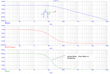
OK, I see it now. How this time delay can define highest practical ULGF in GNFB amp?
edit!
No, that time delay has nothing with ULGF, it influences the frequencies below first pole, and for them it's to small, correct?
edit!
No, that time delay has nothing with ULGF, it influences the frequencies below first pole, and for them it's to small, correct?
Attachments
Last edited:
In feedback delay and phase are both factors contributing to the systems ability to correct itself, we must understand that when we look at it incrementally then the signal that is feed back comes from the open loop, so it can be phase shifted somewhere from 0 up to 180 degree. Within that phase range the vector sum is still subtractive and thus able to correct the signal.. When we let the simulator do its work we get steady state results from a process that really is a state event machine working close to light speed.
If you take an amplifier with a delay of 20 nS then the time to process or to "level balance", means that a 1Hz sine would be corrected 50 million times, or we can weiw the system as digital with a 50 MHz sampling rate and a bit depth approximately corresponding to the loop gain.
If we have a slower amplifier we loose in two ways, the corrective loop takes longer and we loose "sampling rate" and normally the cause of a longer delay is reduced slew rate, that also limits the loop-gain so the bit-depth is lost as well.
If we have a slower amplifier we loose in two ways, the corrective loop takes longer and we loose "sampling rate" and normally the cause of a longer delay is reduced slew rate, that also limits the loop-gain so the bit-depth is lost as well.
Last edited:
Or, you can look at the RC filter's phase response, which is -arctan(2 x Pi x f x RC).
A correction:
This phase response also equals: -arcsin(2 x Pi x f x RC) / arccos(2 x Pi x f x RC).
Since (for small x), arcsin x ~ x, and arccos x ~ 1, then for a small argument <<1, meaning that f << 1/(2 x Pi x RC),
the phase is -(2 x Pi x f x RC) and is linearly proportional to frequency. This linear phase region is the same as a time delay.
A waveform with enough of its lower harmonics << 1/(2 x Pi x RC) would be delayed and its shape preserved.
That is, a waveform after an RC low pass filter (if most of its components are well within the filter's flat bandwidth region)
will be intact, but will also be delayed by (2 x Pi x RC) seconds. This delay is due to a nearly linear phase shift
in the lower part of the pass band range of the RC filter.
Last edited:
The velocity factor of an electric current through a conductor is typically 40 to 90 % of C and highly dependent on the conductors insulation properties (I.e the surrounding sheath). For an amplifier PCB, distributed L and C are low, so current propagation through the circuit is at the upper limit.
Delays of 220ns imply a round trip of around 60 or 70 meters. Does not seem correct.
Secondly, there are a lot of plots of voltage. We should be looking at the current waveforms.
I would expect the total propagation delay to be in the low to mid single digit ns.
What am I missing here?
Someone in the beginning of this thread have suggest that the delay of the amplifier was propagation delay, and I play along, but is now clear that that delay is not propagation delay.
Propagation delay in a " non switching " Power Amplifier will be very low, and maybe less than 1nS .
- Status
- Not open for further replies.
- Home
- Amplifiers
- Solid State
- Feedback loop speed