But at the end the input and output will mach.
What do you mean by this? When there is no input signal?
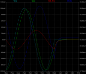
Michael In the third picture #176 look at the moment the impulse stops.
Even that the input voltage is still higher than the output at the moment the impulse stops (30mv), the current in the vas stage is no longer decreasing but starts to increase.
And this goes against your claim that the amplifier always seek lowest possible difference.
But at the end the input and output will mach.
You make an abrupt change to the signal, that will abruptly change the currents, again because it seeks lowest possible differential difference. Again that is "the" control mechanism.
What you show here is that there's no time delay in the feedback loop, despite a clear phase shift
Off course when you make the circuit very slow (limited in slew rate) the loop gain will also be low at the chosen frequency and the ability for tha circuit to balance the two inputs will also be compromised. Make the circuit closer to ideal an see the results.
Last edited:
Sorry Damir, that was a superfluous phrase, and does not help to understand the mechanism. But yes I meant that (+-)5 us after the impulse stop the input and output will be the same at 0V.
Remember, the subtraction which takes place at the feedback summing node is a vector/phasor subtraction, not a simple scalar subtraction. In most cases the signal is not only greatly reduced in size but it is also shifted by approximately 90 degrees.
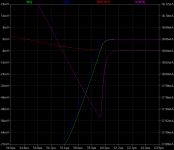
Added the difference between the IN- and IN+
Edit: I think this quate from DF96 at #54 helps Us to understand the mechanism.
Attachments
Last edited:
Added the difference between the IN- and IN+
Edit: I think this quate from DF96 at #54 helps Us to understand the mechanism.
Now do the same with an ideal circuit.
Now do the same with an ideal circuit.
Sorry Michael 🙂, but My goal is to try to understand the feedback mechanism of real amplifiers, I am not personally interested in discussing theories
With a faster amplifier, the results are the same but now with lower delay.
Yes, but now the difference between the two input nodes have lower amplidude because you have a higher Loopgain.
Sorry Michael 🙂, but My goal is to try to understand the feedback mechanism of real amplifiers, I am not personally interested in discussing theories
Then explore the difference between ideal and real, that will give you the right pointers.

Sergio, ask your self why you get the loop gain by comparing the two input nodes.
Why is that..??
Why is that..??
I think that some correspondents are missing the point. Negative feedback will start as soon as the internal amplifier delays permit. There is a delay in the amplifier. My simulations of a simple Miller stabilised amplifier show this. The delay is signal dependent. If the input signal is increased the delay actually reduces, BUT the amplifier then goes into slew rate limiting. Now the differential signal between the input and feedback transistor bases will be large and internally clip the amplifier. The top diagram shows slew rate limiting with a 300nS delay while the small signal delay (below) is 800nS. The output signal is into a resistive divider with the probe at the junction, and where the attenuation is equal to the inverse of the gain so that the voltages are more or less the same level. Once again no-one has volunteered any signal analysis of real music to know whether slew rate limiting is a serious issue or not. I suspect not (Peter Baxandall reported as such many years ago) but it would be useful to see some data.
As regards Jan's question whether it is possible to design an open loop system equivalent to the close loop, in principle, maybe, but the non-linearities of transistors would be very difficult to overcome. This is why negative feedback is so popular! One method might be to analyse the real performance of an amplifier using digital storage and analysis; then devising an inverse algorithm to "predistort" the signal inversely such that when amplified the output is the desired low distortion. But this would have to take many factors into account: transistor non-linear capacitance; gain; transfer characteristics (Ic:Vbe); change with temperature; thermal time constants of the heatsinks and mounting etc etc that I think it would be easier to stick with negative feedback!
As regards Jan's question whether it is possible to design an open loop system equivalent to the close loop, in principle, maybe, but the non-linearities of transistors would be very difficult to overcome. This is why negative feedback is so popular! One method might be to analyse the real performance of an amplifier using digital storage and analysis; then devising an inverse algorithm to "predistort" the signal inversely such that when amplified the output is the desired low distortion. But this would have to take many factors into account: transistor non-linear capacitance; gain; transfer characteristics (Ic:Vbe); change with temperature; thermal time constants of the heatsinks and mounting etc etc that I think it would be easier to stick with negative feedback!

Please don't....
Then you explain the mechanism of feedback..? It's very easy to say others are wrong and then not offer the explanation yourself.
What you have claimed is something like the dog chasing its own tail, that signal delay is the limitation of feedback.
Then what sergio has shown is very clear, despite phase, there's no delay in time. Time delay for audio is a non issue.
The output signal is into a resistive divider with the probe at the junction, and where the attenuation is equal to the inverse of the gain so that the voltages are more or less the same level
Why are they more or less the same level..?? Because the action of feedback into the differential circuit. Equal is the goal, Loopgain sets the limit to how close they can be, and thus also to the precision of the output.
When you compensate an amplifer you set a limit to the slew rate, this in turn limits the possible loop gain and ultimately sets a limit to how high precision you can obtain.
Well, some suggest that there is "no delay". Pavel's measured results and my simulations show there is. What I have shown is that the delay is signal dependent and this is caused by the difference between the input and feedback signals. For small signals, the ability of the differential input stage to drive the Miller capacitor is limited- small voltages equal small currents. The high level input drives more current into the Miller capacitor to the maximum extent it can. In this case one of the input pair conducts twice its normal level while the other is either very low or zero (depending on the differential voltage). So here the feedback is delayed by the slew rate. All I am saying is that I am of the view that there is a delay; it may be small, but that the feedback signal can be signal level dependent.
Then you explain the mechanism of feedback..? It's very easy to say others are wrong and then not offer the explanation yourself.
I am just pointing to the limitations in the explanation using the ideal-amp-with-ideal-feedback-and-ideal-summation-circuit. Once you notice that it's equivalent to an electrostatic arrangement (there are no currents flowing through it and no delays other than light speed limit), you may start to suspect that it's valid only for DC analysis.
Guess you misunderstood my point. The limitation is within the fact that both the amplification A and the delays are dependent on the input signal amplitude too. Ask the OP to use a high input signal that will drive transistors near saturation, and watch how your "amplification reserve" disappears, and how stuff like transistor storage time come into play. Unless your feedback network is adaptive (aka nonlinear too), you could get a circuit latch or oscillations.What you have claimed is something like the dog chasing its own tail, that signal delay is the limitation of feedback.
Then what sergio has shown is very clear, despite phase, there's no delay in time. Time delay for audio is a non issue.
Sure you can design with plenty of headroom, yet the end user playing with the interconnects can produce high amplitude transients beyond your original forecast.
And yes I heard about clamping, but that is nothing than introducing a highly non linear device in the circuit. Trying then to explain the resulting mess using ideal linear circuits is a little bit risqué methinks.
In my opinion we are going in circle here(as well in some other threads).
First of all, simulation (at least what most of us do) does not show time delay, but phase shift between input and output, phase shift because of reactive elements, capacitance, inductance, slew rate. Real time delay is so called propagation delay, very low and can be ignored in audio, and I never saw to be used in any audio simulation. Propagation delay depends on the layout geometry mostly.
Compact layout with short feedback path can give better amp.
Kirchhoff
Those physical boundaries that limits signal amplitude and the slew rate behaves like a signal depending ever changing Loop-gain. These dynamic effects are a reason why we see something like distortion coming from inter modulation. A smal signal ridding on the top af a larger lower frequency signal makes intermittent tones, and intermittent distortion products.
Reason I asked Sergio to try his test with an ideal circuit was that he then will see the difference on the two input nodes become close to non existent, that will help to understand the basic mechanism behind the balance in feedback.
Last edited:
In my opinion we are going in circle here(as well in some other threads).
First of all, simulation (at least what most of us do) does not show time delay, but phase shift between input and output, phase shift because of reactive elements, capacitance, inductance, slew rate. Real time delay is so called propagation delay, very low and can be ignored in audio, and I never saw to be used in any audio simulation. Propagation delay depends on the layout geometry mostly.
Compact layout with short feedback path can give better amp.
Agree. Yet we all have different views. Some still see phase as a delay. It's not, it's just vectorial mathematics. And with phase shift the possible loop gain margin is reduced.
- Status
- Not open for further replies.
- Home
- Amplifiers
- Solid State
- Feedback loop speed